Burr processing jig

A technology of burrs and jigs, which is applied in the field of mechanical processing, can solve the problems of increased sliding resistance of pins, more residues, and affecting the feel of instruments, etc., and achieves the effect of solving burrs, simple use, and simple structure

Inactive Publication Date: 2010-07-21
TOUCHSTONE INTERNATIONAL MEDICAL SCIENCE CO LTD
View PDF1 Cites 3 Cited by
  • Summary
  • Abstract
  • Description
  • Claims
  • Application Information

AI Technical Summary

Problems solved by technology

However, due to the stamping itself, more burrs will be left in the grooves of the stamping parts, which will increase the sliding resistance of the pin and affect the hand feeling of the instrument.

Method used


Image

  • Burr processing jig
  • Burr processing jig
  • Burr processing jig

Examples


Embodiment Construction

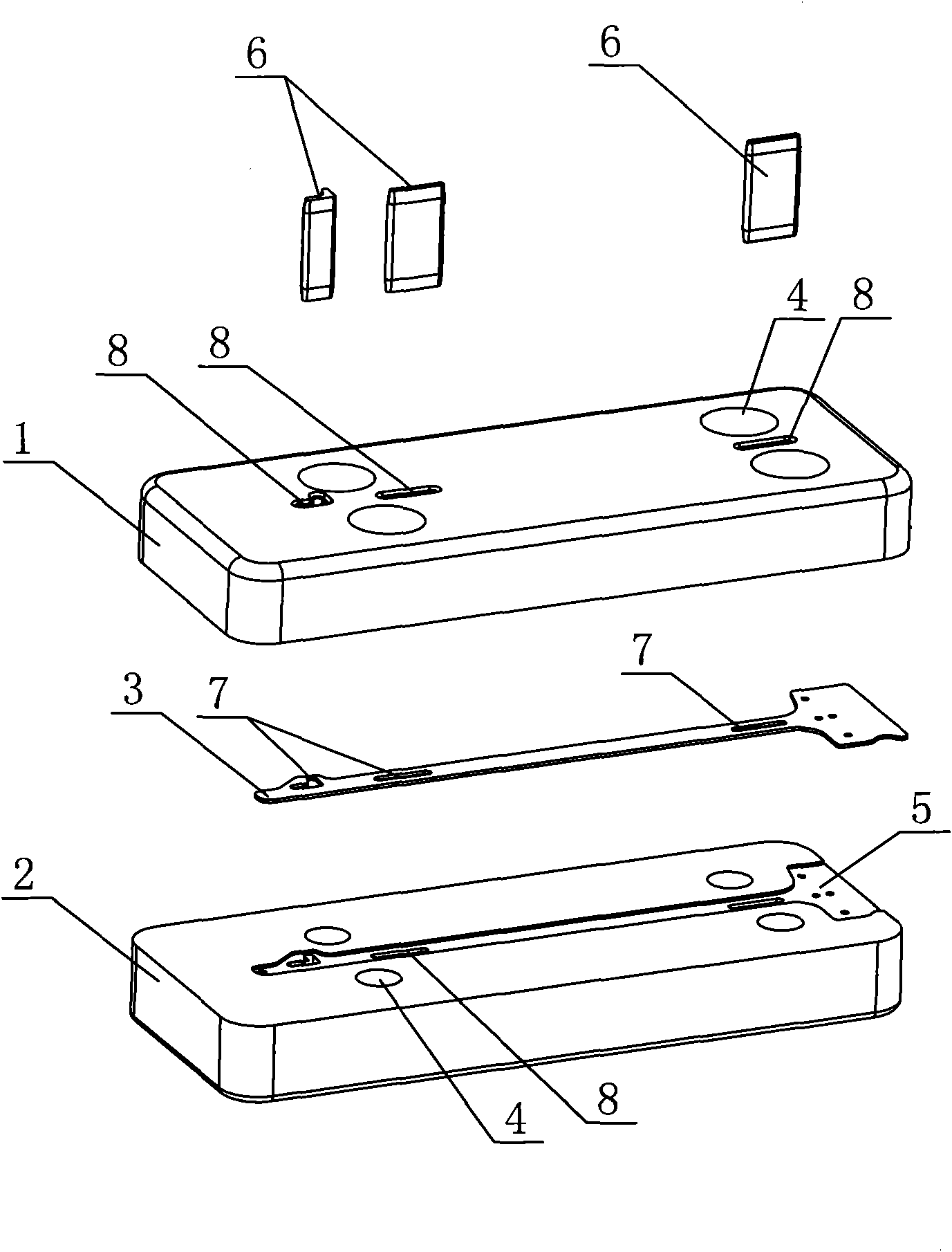
[0020] The invention discloses a burr treatment jig, such as figure 1 As shown, it includes an upper mold 1 and a lower mold 2 detachably connected by fasteners, the fasteners are bolts and nuts, and the upper and lower molds are correspondingly provided with passages for the bolts to pass through. Hole 4.

[0021] The surface of the lower mold 2 is provided with a notch 5 consistent with the outer contour of the workpiece 3 to be processed, and the workpiece 3 to be processed can be placed in the notch 5 .

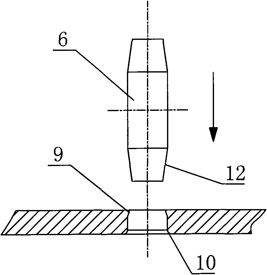
[0022] The deburring jig also includes a punch 6 that can reciprocate between the upper and lower molds, and the punch 6 can be driven by a cylinder or other reciprocating parts. The upper and lower molds 1 and 2 are provided with punching holes 8 for the punches to pass through, and the number and cross-sectional shape of the punches 6 are consistent with the burr holes 7 of the workpiece 3 to be processed. And the number and outline of the punching holes 8 of the uppe...


PUM


Abstract

The invention provides a burr processing jig, which comprises an upper mold and a lower mold which are connected detachably by a fastening piece, and a punch head. The surface of the lower mold is provided with a notch which is consistent with the external contour of a workpiece to be processed, and the workpiece to be processed can be arranged in the notch. The punch head can move between the upper mold and the lower mold in a reciprocating mode. A punched hole for the punch head to pass through is respectively formed on the upper mold and the lower mold. The shape of the cross section of the punch head is consistent with a hole groove with burr of the workpiece to be processed and the contour of the punched holes of the upper mold and the lower mold. The burr processing jig has the advantages that: the structure is simple, the use is simple, and the burr problem of stamped parts can be well solved.

Description

technical field [0001] The invention relates to a jig for deburring stamping parts, which belongs to the technical field of mechanical processing. Background technique [0002] Linear cutting and suturing instruments are widely used in surgical operations for wound suturing, internal tissue suturing and cutting. The instruments generally have two functions of suturing and cutting. While suturing the wound, excess tissue is removed. U.S. Patent No. 6,817,508 discloses a linear stapler, which first clamps the tissue between the anvil and the staple cartridge through the handle arranged on the housing, and then uses the handle again to suture the tissue. [0003] The above-mentioned apparatus adopts more thin-plate stamping parts, such as push bins, push blades, etc., and there are pins sliding in the holes of the above-mentioned stamping parts to control the stroke. However, due to the stamping itself, more burrs will be left in the grooves of the stamping parts, which will i...

Claims


Application Information

Patent Timeline
Patent Type & Authority Applications(China)
IPC IPC(8): B21D22/02
Inventor 陈望东丁水澄
Owner TOUCHSTONE INTERNATIONAL MEDICAL SCIENCE CO LTD
Why Eureka
Try Eureka