High-pressure accumulator of a high-pressure fuel injection system

A high-pressure injection and memory technology, applied in fuel injection devices, special fuel injection devices, charging systems, etc., can solve expensive problems, achieve simple manufacturing, ensure fatigue characteristics, and optimize system efficiency loss

Active Publication Date: 2019-09-13
ROBERT BOSCH GMBH
View PDF6 Cites 2 Cited by
  • Summary
  • Abstract
  • Description
  • Claims
  • Application Information

AI Technical Summary

Problems solved by technology

In this case, a costly additional post-processing of the insertion diameter is re

Method used


Image

  • High-pressure accumulator of a high-pressure fuel injection system
  • High-pressure accumulator of a high-pressure fuel injection system
  • High-pressure accumulator of a high-pressure fuel injection system

Examples


Embodiment Construction

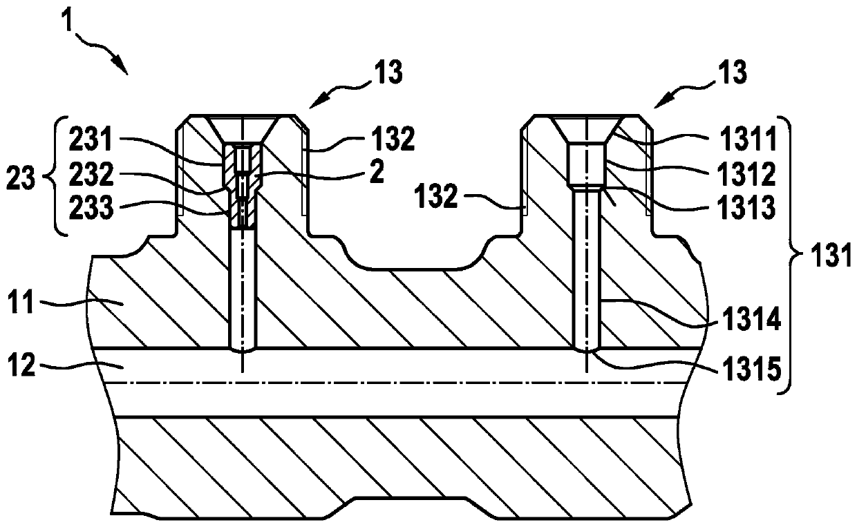
[0037] according to figure 1 , the invention relates to a rail or high-pressure accumulator 1 of a high-pressure injection system in an internal combustion engine. Common parts of the rail are shown in axial section. Other parts of the spraying device are not shown.

[0038] The high-pressure accumulator 1 is a thick-walled cylindrical body 11 made of forged steel, which encloses a high-pressure chamber 12 supplied with high-pressure fuel by a high-pressure pump in order to distribute the high-pressure fuel to injection valves (injectors) , the injection valve is controlled by the central control unit of the engine.

[0039] The closing and opening movements of the injectors generate compression and decompression waves ("pressure shocks") which are transmitted from the high pressure fluid into the piping connecting the injectors to rail 1 and thus into the rail.

[0040] The cylindrical body 11 has connection pieces 13 for connection, which are each connected via a channel...


PUM


Abstract

The invention relates to a high-pressure accumulator for a high-pressure injection system made of a cylindrical body (11), which delimits a high-pressure chamber (12, 12a), and connection pieces (13,13a), which are provided with outlet passages (131, 131a) for a high-pressure liquid, said passages opening into the chamber (12, 12a), and each of which is provided with a throttle in order to weakenpressure waves generated by injectors connected downstream. Each of the connection pieces (13, 13a) has a passage (131, 131a) with a chamber (1312, 1312a) at the outlet, said chamber receiving an insert piece (2, 2a) which is provided with the throttle (22, 22a). The insert piece (2, 2a) is fixed in the chamber (1312, 1312a) in a force-fitting manner by an autofrettage process of the high-pressure accumulator.

Description

technical field [0001] The invention relates to a high-pressure accumulator for a high-pressure injection system, consisting of a cylindrical body delimiting a high-pressure chamber and a connecting piece provided with an outlet channel for the high-pressure fluid leading into the chamber and provided with There is a throttle in order to attenuate the pressure waves generated by the injectors connected downstream. Background technique [0002] known in Figure 7 The high-pressure accumulator of such a high-pressure injection system is shown in . The rail 100 , also referred to as “high-pressure accumulator”, is formed by a cylindrical body 111 made of thick forged steel, which surrounds a high-pressure chamber 112 . The body of the rail has outlet connections 113 for connecting high-pressure lines, which are connected to one injector each. The connecting piece 113 is penetrated by a hole 114 leading into the chamber 112 . On the base of the hole there is a bored restricti...

Claims


Application Information

Patent Timeline
IPC IPC(8): F02M55/02F02M55/04
CPCF02M55/025F02M55/04F02M2200/28F02M2200/8069F02M2200/315
Inventor P·阿利奥
Owner ROBERT BOSCH GMBH
Why Eureka
Try Eureka