Flat key and locking machine

A key, flat technology, applied in the field of flat keys and locks, can solve the problems of high technological requirements for production and processing, complex internal structure, etc., to achieve the effect of compact structure, high production efficiency, and improved coding rate

Inactive Publication Date: 2010-07-21
SICHUAN SHENGBAO ELECTRICAL TECH
View PDF1 Cites 0 Cited by
  • Summary
  • Abstract
  • Description
  • Claims
  • Application Information

AI Technical Summary

Problems solved by technology

The lock described in this patent uses the guide groove on the flat surface of the key to push the slider to move, which increases the code change rate in a small key space and improves the safety performance of the lock. However, its internal structure is relatively complicated, and production and processing higher process requirements

Method used


Image

  • Flat key and locking machine
  • Flat key and locking machine
  • Flat key and locking machine

Examples


Embodiment Construction

[0025] The present invention will be further described below in conjunction with the accompanying drawings and embodiments.

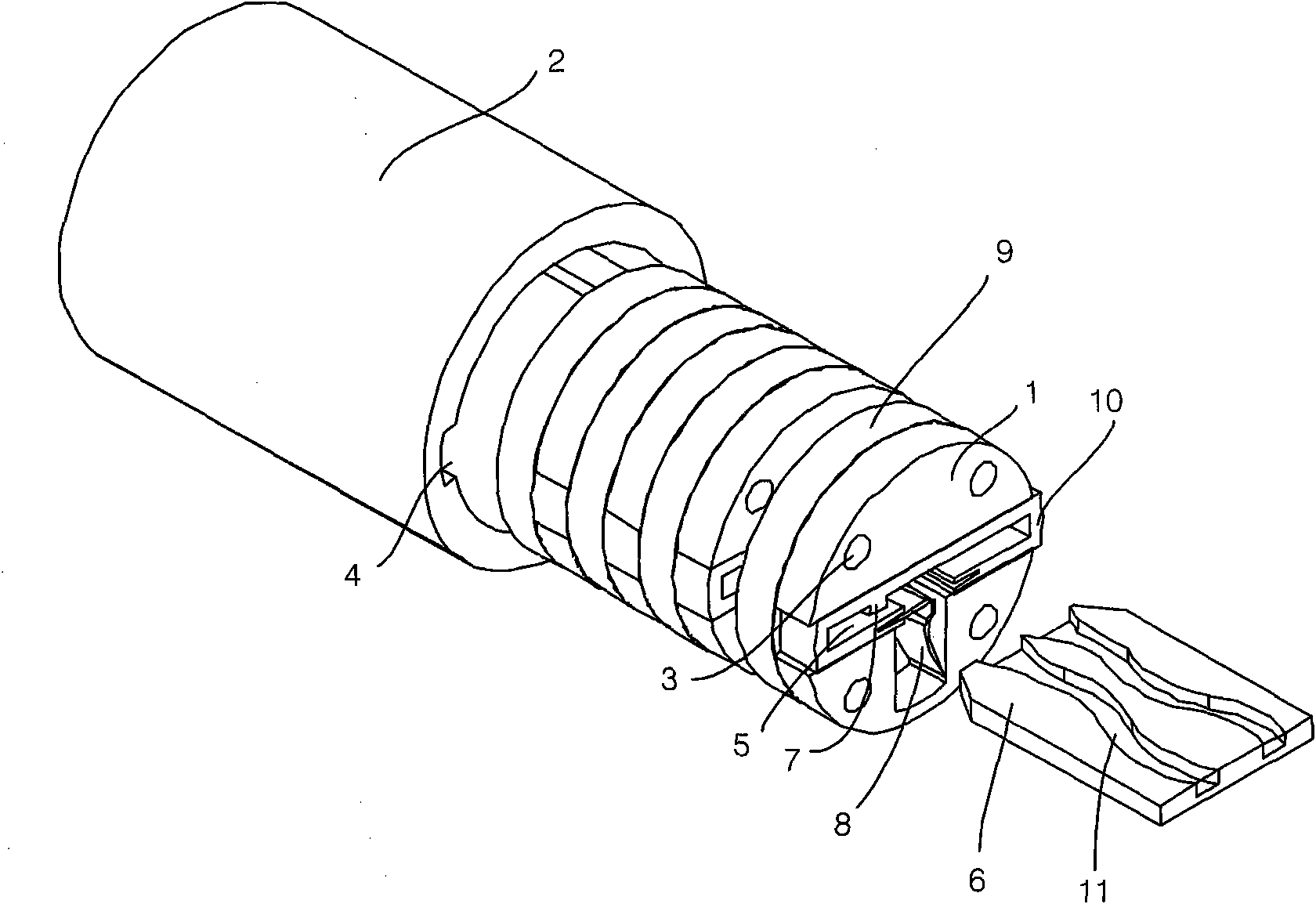
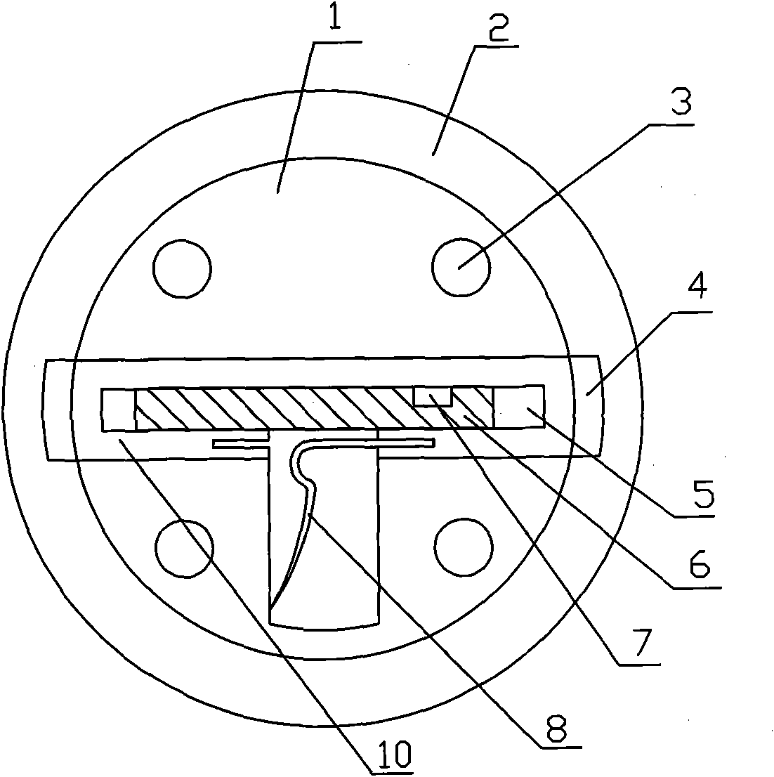
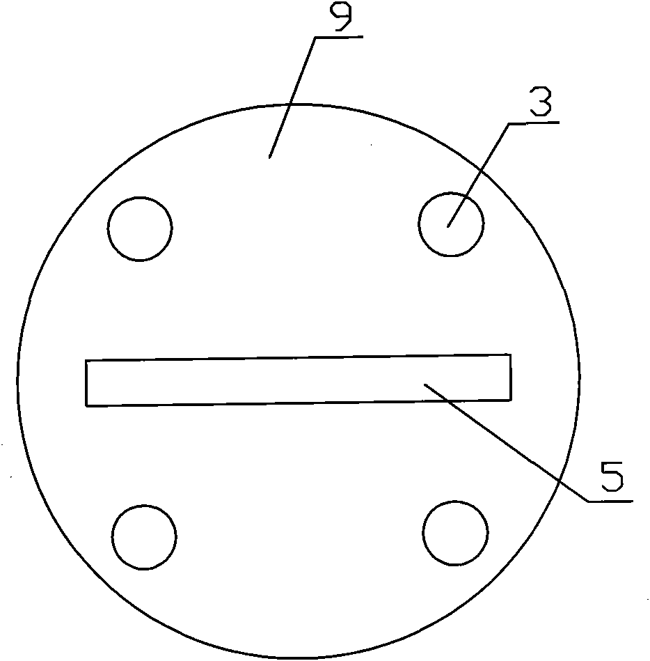
[0026] Specific embodiment 1 of the present invention, as figure 1 , 2 , shown in 3, a kind of flat key and lock machine, comprise flat key, shell 2, the rotatable lock core in shell 2, be formed with curved guide groove 11 on the flat surface of one side of flat key 6, along guide groove 11 Identification points are distributed, and a slide block 10 is installed in the lock cylinder. On the face opposite to the key, the slide block 10 is provided with a guide column 7 cooperating with the guide groove 11. Correspondingly, each slide block 10 is provided with a For the grooves 4, the two grooves 4 in each pair of grooves 4 are respectively located at both ends of the slider 10, and in the locked state, one of the two ends of the slider 10 slides into the groove in the housing 2 In 4, when unlocking, the key pushes the guide column 7 to drive the slide...


PUM


Abstract

The invention discloses a flat key and a locking machine, comprising a flat key, a shell and a rotatable lock core in the shell. A bending guide groove is formed on a flat surface on at least one lateral surface of the flat key; identification points are distributed along the guide groove; a sliding block is arranged in the lock core; guide posts matched with the guide grooves are arranged on the surface relative to the key of the sliding block; the inner wall of the shell is provided with a pair of grooves corresponding to each sliding block; two grooves in each pair of grooves are respectively positioned at two ends of the sliding block; one sliding block in two end parts of the sliding block enters the groove of the shell in the locked state; during unlocking, the sliding block is driven by pushing the guide posts through the key to move, so that the sliding block is positioned at the unlocking position in the middle of two grooves, both two end parts of the sliding block are positioned outside the grooves and the lock between the lock core and the shell can be removed; and a return spring for pushing the sliding block to leave from the unlocking position is arranged between the sliding block and the lock core. The flat key and the locking machine have the advantages of simple structure, high production efficiency, high code rate, safety and reliability.

Description

technical field [0001] The invention relates to lock technology, in particular to a high-safety flat key and a lock machine. Background technique [0002] Usually, the key of the lock is coded on the side of the key, and the jagged projections on the side of the key push the movement of the marble in the lock, and the lock is opened when the decoding condition is met. Taking a tumbler lock and key as an example, the key is coded, and 7 identification positions and 5 reading depths are set along the side of the key. Therefore, in theory, the mutual opening rate of the lock and key is at least 1 / 5 7 , that is 0.001%, and it is easy to open with a non-matching key unlocking tool. [0003] In order to increase the complexity of lock coding, thereby improving the security level of locks, a variety of locks with different coding mechanisms have been produced. As described in the U.S. patent, publication number US2006 / 0236733, a flat key and a lock machine have a pair of zigzaggi...

Claims


Application Information

Patent Timeline
Patent Type & Authority Applications(China)
IPC IPC(8): E05B19/00E05B63/00
Inventor 沈晓槎周小森
Owner SICHUAN SHENGBAO ELECTRICAL TECH
Why Eureka
Try Eureka