Shear spring

A technology of shearing springs and elastic materials, applied in the direction of springs/shock absorbers, springs made of plastic materials, mechanical equipment, etc., can solve the problems of small force, vibration strength, inapplicability, and rubber strength is not very high, etc. To achieve the effect of safe and reliable use, long life and convenient installation

Active Publication Date: 2010-07-21
鞍山鞍重矿山机械有限公司
View PDF0 Cites 2 Cited by
  • Summary
  • Abstract
  • Description
  • Claims
  • Application Information

AI Technical Summary

Problems solved by technology

Since this connection method is not very firm, and the strength of the rubber is not very high, it can only be used in occasions with light weight, low force and low vibration intensity.
If the force and vibration intensity are large, this kind of shear spring is not suitable

Method used


Image

  • Shear spring
  • Shear spring
  • Shear spring

Examples


Embodiment Construction

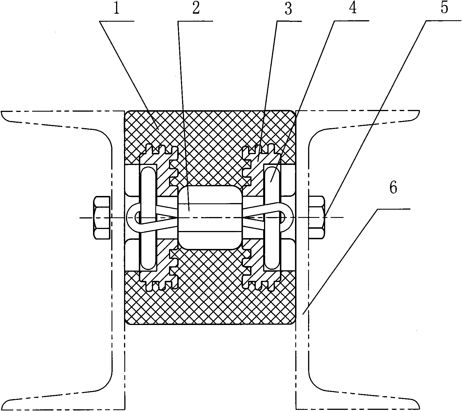
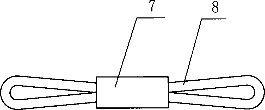
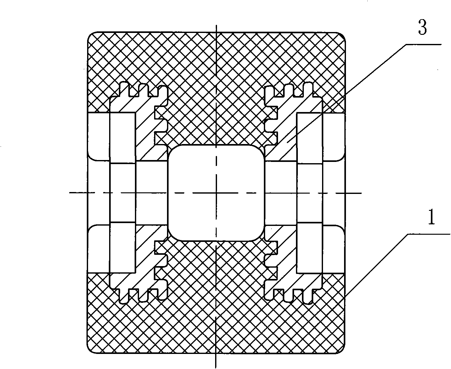
[0008] The embodiment of the present invention will now be described in conjunction with the accompanying drawings. The shear spring body 1 is a cylinder formed of polyurethane material with a hole in the middle, and two metal mounting claws 3 are pre-embedded near the two ends of the interior. 3. Threaded holes 9 for installation are processed on the top; grooves or columnar protrusions that can increase the contact surface with the polyurethane spring body are processed on the circumference and end faces. The two mounting jaws 3 are connected together by a safety wire ring 2, and the two ends are fixed by positioning pins 4. Insurance wire ring 2 is to be made by multi-strand wire rope 8, and two ends are bent to be ring-shaped, and the center is locked by pressing joint 7. When the shear spring is in use, the two end faces of the spring can be connected with the corresponding parts 6 with connecting bolts 5 .


PUM


Abstract

The invention provides a shear spring, which belongs to the field of general mechanical components and is designed for overcoming the deficiency that the prior rubber shear spring is low in strength and poor in bearing capacity. A main body of the shear spring is a cylinder which is made from nonmetal elastic materials and is provided with a hole in the middle; two metal installation claw discs are pre-embedded inside a spring body near two end faces of the spring body; the installation claw discs are provided with threaded holes for installation and use; the two installation claw discs are connected together through a safety steel wire ring; and two ends of the installation claw discs are fixed by positioning pins. The shear spring has the characteristics of convenient installation, safe reliable use and long lifespan, and can be widely applied to vibrating-screening or feeding machines or other equipment with high acting force and vibration intensity in industrial and mining enterprises.

Description

technical field [0001] The invention belongs to the field of general mechanical parts, and mainly relates to a shear spring with high strength and safety. Background technique [0002] In the existing rubber shear springs, the two ends of the rubber spring body are generally glued to the connecting plate, or formed together with the connecting plate, and fixed to the corresponding workpiece through the connecting plate. The two ends of the rubber spring body can also be placed in the pit of the connecting plate, and fixed to the corresponding workpiece through the connecting plate. Since this connection method is not very firm, and the strength of the rubber is not very high, it can only be used in occasions with light weight, low force and low vibration intensity. If the force and vibration intensity are large, this kind of shear spring is not suitable. Contents of the invention [0003] The object of the present invention is to provide a shear spring, which can effecti...

Claims


Application Information

Patent Timeline
Patent Type & Authority Applications(China)
IPC IPC(8): F16F1/50
Inventor 孙海军王琦玮
Owner 鞍山鞍重矿山机械有限公司
Why Eureka
Try Eureka