Front luggage rack check tool

A luggage rack and inspection tool technology, applied in the field of tooling and fixtures, can solve the problems of inaccurate grasp of the quality of the front luggage rack, inability to install the front luggage rack, and lax quality control at the factory, so as to improve the speed of quality inspection. and accuracy, meet consistent production, and ensure the effect of assembly efficiency

Inactive Publication Date: 2011-06-29
力帆科技(集团)股份有限公司
View PDF0 Cites 0 Cited by
  • Summary
  • Abstract
  • Description
  • Claims
  • Application Information

AI Technical Summary

Problems solved by technology

When receiving the front luggage racks from supporting manufacturers, all motorcycle manufacturers rely on the experience of workers to check the overall shape, length and size of the front luggage racks, as well as the positions of the three mounting holes and the two connecting holes of the front luggage case. , size, etc. In this way, the quality of the front luggage rack is not accurately grasped, and it is easy to cause the quality control of the factory to be lax
If there is a size deviation in the assembly part of the front luggage rack, the front luggage rack cannot be installed on the front cover mounting bracket, or the front luggage rack interferes with the front cover mounting bracket, or the front luggage rack cannot be installed, etc., resulting in heavy rework. Unnecessary troubles such as manufacturing and returning goods; although some front luggage racks can be barely installed by modifying the size of the installation part, it will inevitably affect the assembly efficiency and fail to meet the requirements of consistent production

Method used


Image

  • Front luggage rack check tool
  • Front luggage rack check tool
  • Front luggage rack check tool

Examples


Embodiment Construction

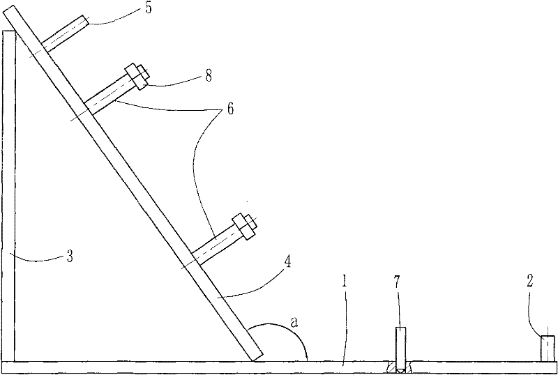
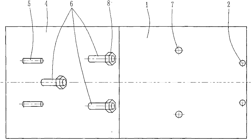
[0015] Below in conjunction with accompanying drawing and embodiment the present invention will be further described:

[0016] Such as figure 1 , figure 2 Shown, the present invention is made of parts such as base plate 1, first stop bar 2, riser 3, swash plate 4, second stop bar 5, first stop bar 6, second stop bar 7 and nut 8. Wherein the bottom plate 1 is a rectangular plate structure, in the bottom plate 1 such as figure 1 , 2 The shown right end plate is provided with two first limit rods 2 side by side in front and back, the first limit rods 2 are fixed vertically to the bottom plate 1, and the two first limit rods 2 are symmetrically distributed on the length of the bottom plate 1 The two sides of the center line of the direction, and the line connecting the centers of the two first limit rods 2 is perpendicular to the long side of the bottom plate 1. A riser 3 is vertically fixed on the board surface of the left end of the base plate 1, and the top of the riser 3 ...


PUM


Abstract

The invention disclose a front luggage rack check tool, which is characterized in that a soleplate is of a rectangular flat plate structure, the surface on one end of the soleplate is provided with a first limiting rod, the surface on the other end of the soleplate is vertically provided with a vertical plate, the top part of the vertical plate is fixedly connected with the upper end of an oblique plate, and the lower end of the oblique plate is supported by the middle part of the soleplate; the surface on the upper part of the oblique plate is provided with a second limiting rod, three firstpositioning rods which are distributed in an isosceles triangle shape are arranged below the second limiting rod, the first positioning rods are vertically fixed on the oblique plate, the soleplate between the oblique plate and the first limiting rod is provided with two second positioning rods in parallel, and the second positioning rods are vertical to the soleplate. With the front luggage rackcheck tool, the shop quality inspection speed and accuracy of the front luggage rack of the motorcycle enterprise can be greatly improved, the quality of the front luggage rack can be ensured to conform to the requirements, the assembling speed of the front luggage rack can be effectively improved, and the consistent production requirement can be satisfied. The front luggage rack check tool has the advantages of reasonable design, simple and reliable structure, easy operation and the like.

Description

technical field [0001] The invention belongs to the technical field of fixtures, and in particular relates to a detection device for a front luggage rack of a motorcycle. Background technique [0002] The front luggage rack is a connecting part on the motorcycle, which is fixed on the front cover mounting bracket on the frame and is used for installing the front luggage basket. The front luggage rack is usually a frame structure consisting of a horizontal section at the front and a sloped section at the rear. Three installation holes distributed in an isosceles triangle are arranged on the inclined section of the front luggage rack, and these three installation holes are connected with the front mask installation bracket by bolts. Two front luggage basket connection holes are arranged side by side on the horizontal section of the front luggage rack for the assembly of the front luggage case. At present, the front luggage rack is generally produced by supporting manufacture...

Claims


Application Information

Patent Timeline
Patent Type & Authority Patents(China)
IPC IPC(8): G01B5/00G01B5/24
Inventor 付凤雄韩旭东
Owner 力帆科技(集团)股份有限公司
Why Eureka
Try Eureka