Suspension structure of pendent tube used for S-shaped tube panel

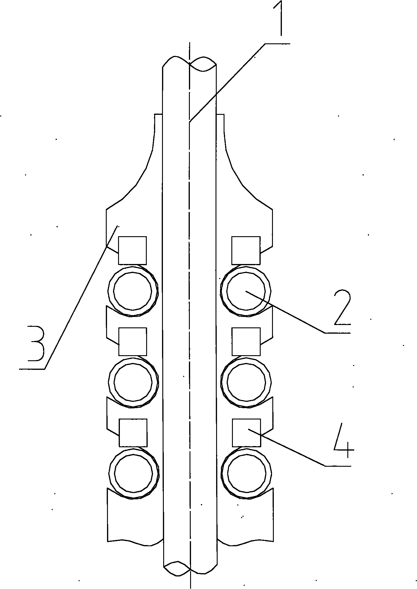
A suspension structure and suspension pipe technology, which is applied in the direction of boiler support/positioning device, etc., can solve the problems of difficulty in fine processing of zigzag brackets 3, easy to leave hidden dangers, and inability to apply, etc., and achieves convenient processing and installation. The effect of preventing the tube from going out of line and having a simple structure

Active Publication Date: 2010-07-28
SHANGHAI BOILER WORKS
View PDF0 Cites 16 Cited by
  • Summary
  • Abstract
  • Description
  • Claims
  • Application Information

AI Technical Summary

Problems solved by technology

[0004] Although this structure is compact, it is difficult to install due to the difficulty in the fine machining of the zigzag support block 3, and it is easy to leave hidden dangers, which may cause the horizontal pipe system 2 pipes to be out of line during operation.
Secondly, this structure is restricted by the zigzag support block 3 and can only be used in the serpentine tube row with the same upper and lower spacing of the horizontal piping system 2, and the spacing cannot be too small. It cannot be applied to the horizontal tube panel with a small spacing

Method used


Image

  • Suspension structure of pendent tube used for S-shaped tube panel
  • Suspension structure of pendent tube used for S-shaped tube panel
  • Suspension structure of pendent tube used for S-shaped tube panel

Examples


Embodiment

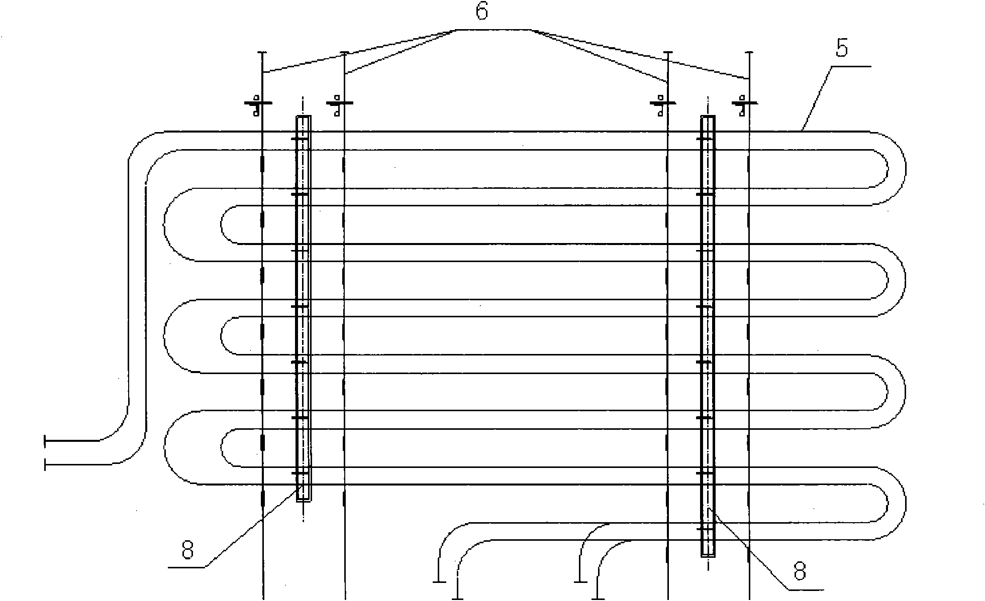
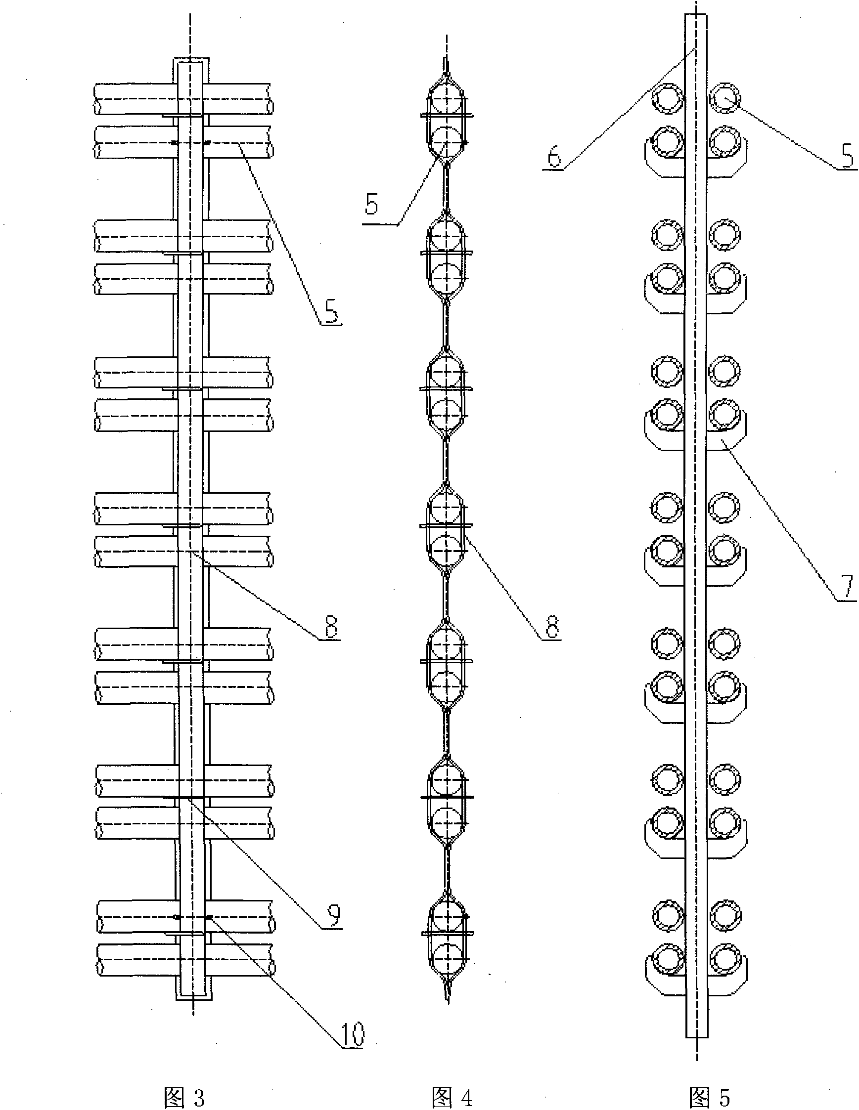
[0022] The invention provides a suspension tube suspension structure for a serpentine tube panel, which is realized in the form of suspension tube + pipe clamp. Such as image 3 and Figure 4 Shown is a schematic diagram of the tube clamp section, Figure 5 A schematic diagram of the suspension tube part. The following combination Figure 2 to Figure 5 To illustrate the present invention, it includes two pipe clips 8 buckled on the tube panel 5, the width of the two pipe clips 8 is not the same to facilitate welding, a steel plate 9 is inserted in the pipe clip 8, and the two sides of the pipe clip 8 are respectively A suspension pipe 6 is provided, and a supporting steel plate 7 for supporting the tube panel 5 is horizontally provided on the suspension pipe 6 .

[0023] The suspension pipe 6 only plays the role of transmitting the gravity of the tube panel 5, and the weight is transmitted through the supporting steel plate 7, while the tube clamp 8 installed on the tube p...


PUM


Abstract

The invention relates to a suspension structure of a pendent tube used for an S-shaped tube panel. The invention is characterized in that the suspension structure comprises two tube clamps buckled on the tube panel oppositely; a steel plate is inserted in each tube clamp; the two sides of the tube clamp are respectively provided with one pendent tube; and a supporting steel plate used for supporting the tube panel is horizontally arranged on the pendent tube. The suspension structure has the advantages that due to the simple structure, the pendent tube is processed and installed more conveniently; the number of the tube clamp can be increased or decreased according to the actual situation, thereby effectively preventing the tube clamps from leaving the rank; and whether the space between tubes in the tube panel is regular or not, the tube panel can be suspended on the pendent tube by adjusting the stressed point by the tube clamps in different specifications.

Description

technical field [0001] The invention relates to a suspension structure for reducing the swing of the tube panel and transferring the weight of the horizontal tube. Background technique [0002] The fluctuating flue gas flow scours the tube panel to cause swing, and the swinging tube panel interferes with the flue gas flow and continuously absorbs energy from the flue gas flow, so the swing of the tube panel is difficult to stop. The swing of the tube panel will cause alternating bending stress at the fixed root of the tube panel, causing fatigue damage, and may also collide with each other to cause wear and tear damage; on the other hand, the fluctuation of the flue gas will also cause some tubes in the tube panel to go out. , resulting in wear damage or local overheating. A certain suspension structure is required. At the same time, for the safe operation of the pipes, the weight of the horizontal pipes needs to be safely transferred in a certain hoisting method according...

Claims


Application Information

Patent Timeline
Patent Type & Authority Applications(China)
IPC IPC(8): F22B37/24
Inventor 李立薛凌云赵井冈杨秀萍
Owner SHANGHAI BOILER WORKS
Why Eureka
Try Eureka