Fin rotating mechanism capable of dynamically measuring fin lift force

A dynamic measurement and lift technology, which is applied in the direction of measuring force, measuring device, and using hydrofoils to reduce the movement of ships on the surrounding water surface. It can solve problems such as fin lift deviation and fluid dynamic complexity, so as to improve accuracy and eliminate hysteresis characteristics. , the effect of easy maintenance

Inactive Publication Date: 2012-06-06
哈尔滨哈船减摇自动化设备有限公司
View PDF0 Cites 0 Cited by
  • Summary
  • Abstract
  • Description
  • Claims
  • Application Information

AI Technical Summary

Problems solved by technology

Due to the complexity of the fluid dynamics on the fin surface and the interference of various complex factors, there is a large deviation in the lift force generated by the fin estimated by the angle

Method used


Image

  • Fin rotating mechanism capable of dynamically measuring fin lift force
  • Fin rotating mechanism capable of dynamically measuring fin lift force
  • Fin rotating mechanism capable of dynamically measuring fin lift force

Examples


specific Embodiment approach 1

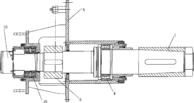
[0040] combine Figure 4 and Figure 5 , on the basis of the traditional fixed fin stabilizer and fin rotation device, the fin shaft in the whole device adopts the hollow fin shaft 2, and a real shaft core 7 is arranged inside the fin shaft, and the shaft core 7 is connected with the fin shaft near the fin installation position The jacket is tightly connected and can rotate with the fin shaft. To fin shaft, adopt double fulcrum to fix, promptly last support bearing 15, following support bearing 4, and last support bearing 15, following support bearing 4 are all enclosed within on the fin shaft 2 overcoats, axle core 7 does not directly contact with up and down support bearing. In addition, the shaft sleeve 3 is used to fix the lower support bearing 4, and the box body 5 is welded on the hull to fix the entire mechanical structure of the fin. The rotation of the fins is figure 2 The rocker arm 6 in the drive is driven by a power mechanism.

[0041] The lift measurement sens...

specific Embodiment approach 2

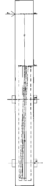
[0059] combine Figure 6 and Figure 7 , the second embodiment of the present invention is based on the first embodiment, the lift measurement sensor adopts an installation method based on the lift characteristics of the fin.

[0060] When measuring based on the lift characteristic of the fin, a right-angle transmission rod 19 is fixedly installed at the end of the shaft core 7, and an arc-shaped gap is cut on the shell of the fin shaft in addition. shaft, while rotating with the fin shaft without touching the fin shaft. In addition, an arc-shaped induction block 20 is installed at the end of the transmission rod 19, and the arc-shaped induction block 20 can rotate with the fin shaft. Along the lift direction of the fin, a small hole is opened on the side wall of the bearing gland 18, and a fixed lift measuring sensor 21 is installed, which still adopts a non-contact displacement sensor.

[0061] After the lift measuring sensor is installed, along the Figure 6 Middle B-B ...


PUM


Abstract

The invention provides a fin rotating mechanism capable of dynamically measuring fin lift force, which comprises a fin shaft, wherein an end fin sleeve of the fin shaft is provided with an anti-rolling fin; an end circle center position at the other end of the fin shaft is provided with a potentiometer type fin angle measuring transducer to form a fin angle feedback box to serve as a fin angle feedback mechanism; the fin shaft realizes double-support fixation through two bearings; a box body realizes dynamic seal with the fin shaft and is welded on a boat hull; the fin shaft is a hollow fin shaft, and a solid shaft core is arranged in the hollow fin shaft, is firmly connected with a jacket of the fin shaft close to a fin mounting position and can rotate along with the fin shaft; and a lift force measuring transducer is fixedly arranged at the tail end of the solid shaft core. The fin rotating mechanism designed by the invention can directly acquire the dynamic lift force of a fin, avoid the non-linear relationship between an angle of attack and the lift force, and reduce the phase lag caused by the angle of attack in an angle servo.

Description

technical field [0001] The invention relates to a control device for fins of ships and other marine or space moving bodies. Background technique [0002] Traditional fixed fin stabilizer and fin-rotating mechanism such as figure 2 As shown, the fin shaft in this mechanism is a solid shaft, and one end of the fin shaft passes through figure 2 The middle fin sleeve 1 is equipped with a stabilizer fin, and a potentiometer-type fin angle measurement sensor is installed at the center of the other end of the fin shaft to form a fin angle feedback box 10 as a fin angle feedback mechanism. The fin shaft adopts bearings 4 and 15 to realize double support and fixation, the box body 5 and the fin shaft realize dynamic sealing, and the box body 5 is welded on the hull. The rocker arm 6 is driven by the power mechanism to drive the fin shaft to rotate, thereby realizing the rotation of the fin. During the operation of this mechanism, the fin angle can be dynamically measured through t...

Claims


Application Information

Patent Timeline
Patent Type & Authority Patents(China)
IPC IPC(8): B63B39/06G01L1/00G01B21/32
Inventor 梁利华吉明张松涛王经甫史洪宇马鉴恩宋吉广杨生金鸿章
Owner 哈尔滨哈船减摇自动化设备有限公司
Why Eureka
Try Eureka