Non-going-forward device for small-pitch stepper cooling bed
A step-by-step, tooth-pitch technology, applied in cooling beds, metal processing equipment, metal rolling, etc., can solve problems affecting the quality of steel pipes, bending deformation of hot steel pipes, etc.
Inactive Publication Date: 2010-08-11
TAIYUAN HEAVY IND
View PDF0 Cites 9 Cited by
- Summary
- Abstract
- Description
- Claims
- Application Information
AI Technical Summary
Problems solved by technology
The purpose of the present invention is to overcome the shortcomings of the prior art and provide a stepping device for a step-by-step cooling bed with a small tooth pitch to solve the problem that when the steel pipe needs to stay on the cooling bed, the hot steel pipe will be bent and deformed, which will affect the quality of the steel pipe
Method used
View moreImage
Smart ImageViewing Examples
Examples
Embodiment Construction
Login to View More PUM
 Abstract
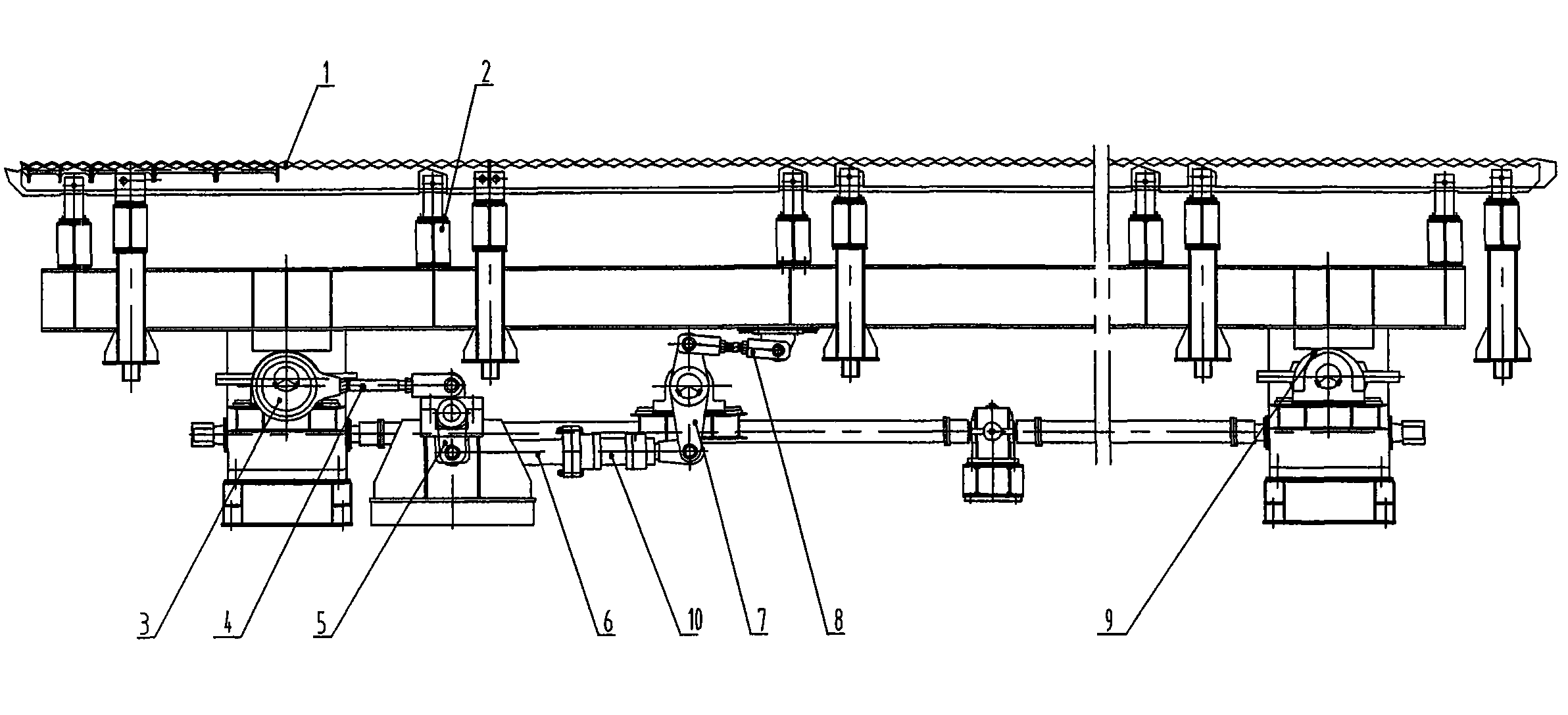
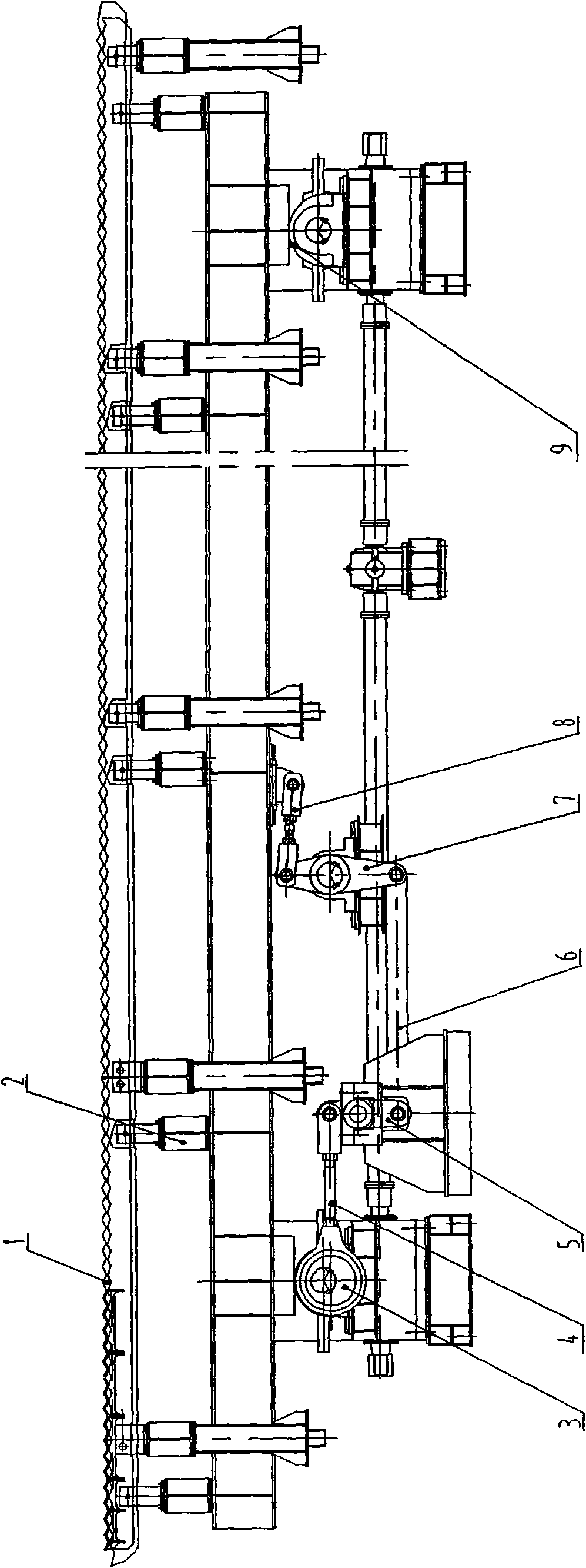
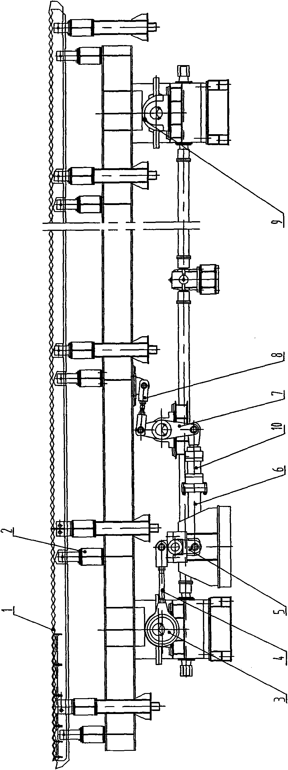
The invention discloses a non-going-forward device for a small-pitch stepper cooling bed, and relates to hot-rolled steel pipe cooling equipment. The invention comprises a fixed rack, a movable rack and a transmission mechanism, wherein the movable rack is supported by two groups of No.I eccentric wheels, and a group of No.II eccentric wheels drive the movable rack through a connecting rod, a lever, a pull rod and a rocker; and a group of eccentric wheels of the two groups of No.I eccentric wheels and the No.II eccentric wheels are coaxial, and a motor is driven by a speed reducer, so that the movable rack moves along the elliptical trajectory. The invention is characterized in that the pull rod between the lever and the rocker is connected with a hydraulic cylinder in series. The invention solves the problems that hot steel pipes bends and deforms to affect the quality of the steel pipes when the steel pipes need to stay on the cooling bed. When the steel pipes stay on the cooling bed, the steel pipes can roll in the rack of the cooling bed and can not go forward, so that the steel pipes can be straightened when being cooled.
Description
Stepping device for stepping cooling bed with small tooth pitch technical field The invention belongs to cooling equipment for hot-rolled steel pipes, in particular to a transmission device for a small-tooth-pitch step-type cooling bed in a seamless steel pipe production unit. Background technique The step-by-step cooling bed with small tooth pitch is installed behind the sizing (reducing) machine, and accepts the hot-rolled steel pipe output by the sizing (reducing) machine, cools it to the required temperature, and transports it to the next station. The small pitch step-type cooling bed device of prior art is shown in Figure 1, comprises: fixed rack 1, moving rack 2 and its transmission mechanism, moving rack 2 is supported by two groups of No. I eccentric wheels 9, by A group of No. II eccentric wheels 3 drives the mobile rack 2 through the connecting rod 4, lever 5, pull rod 6, rocker 7, and adjusting pull rod 8; Coaxial, and driven by the motor through the reducer, t...
Claims
Login to View More Application Information
Patent Timeline
 IPC IPC(8): B21B43/00
Inventor 赵玉洁
Owner TAIYUAN HEAVY IND
Features
- R&D
- Intellectual Property
- Life Sciences
- Materials
- Tech Scout
- Unparalleled Data Quality
- Higher Quality Content
- 60% Fewer Hallucinations
Learn More Browse by: Latest US Patents, China's latest patents, Technical Efficacy Thesaurus, Application Domain, Technology Topic, Popular Technical Reports.
© 2025 PatSnap. All rights reserved.Legal|Privacy policy|Modern Slavery Act Transparency Statement|Sitemap|About US| Contact US: help@patsnap.com


