Base plate, contact ring, lipseal, electroplating device and electroplating method

A technology for base plates and sealing parts, applied in sealing devices, circuits, electrolytic components, etc., can solve the problems of particle contamination at the edge of the wafer, damage to the wafer, etc.

Active Publication Date: 2010-08-11
NOVELLUS SYSTEMS
View PDF9 Cites 47 Cited by
  • Summary
  • Abstract
  • Description
  • Claims
  • Application Information

AI Technical Summary

Problems solved by technology

Electrolyte in the contact area can also cause damage to th...

Method used


Image

  • Base plate, contact ring, lipseal, electroplating device and electroplating method
  • Base plate, contact ring, lipseal, electroplating device and electroplating method
  • Base plate, contact ring, lipseal, electroplating device and electroplating method

Examples


Embodiment Construction

[0042] In the following description, numerous details are set forth in order to provide a thorough understanding of the invention. The present invention may be practiced without some or all of these details. In other instances, well known process operations have not been described in detail in order not to unnecessarily obscure the present invention. While the invention will be described in conjunction with specific embodiments, it will be understood that it is not intended to limit the invention to the described embodiments.

[0043] introduction

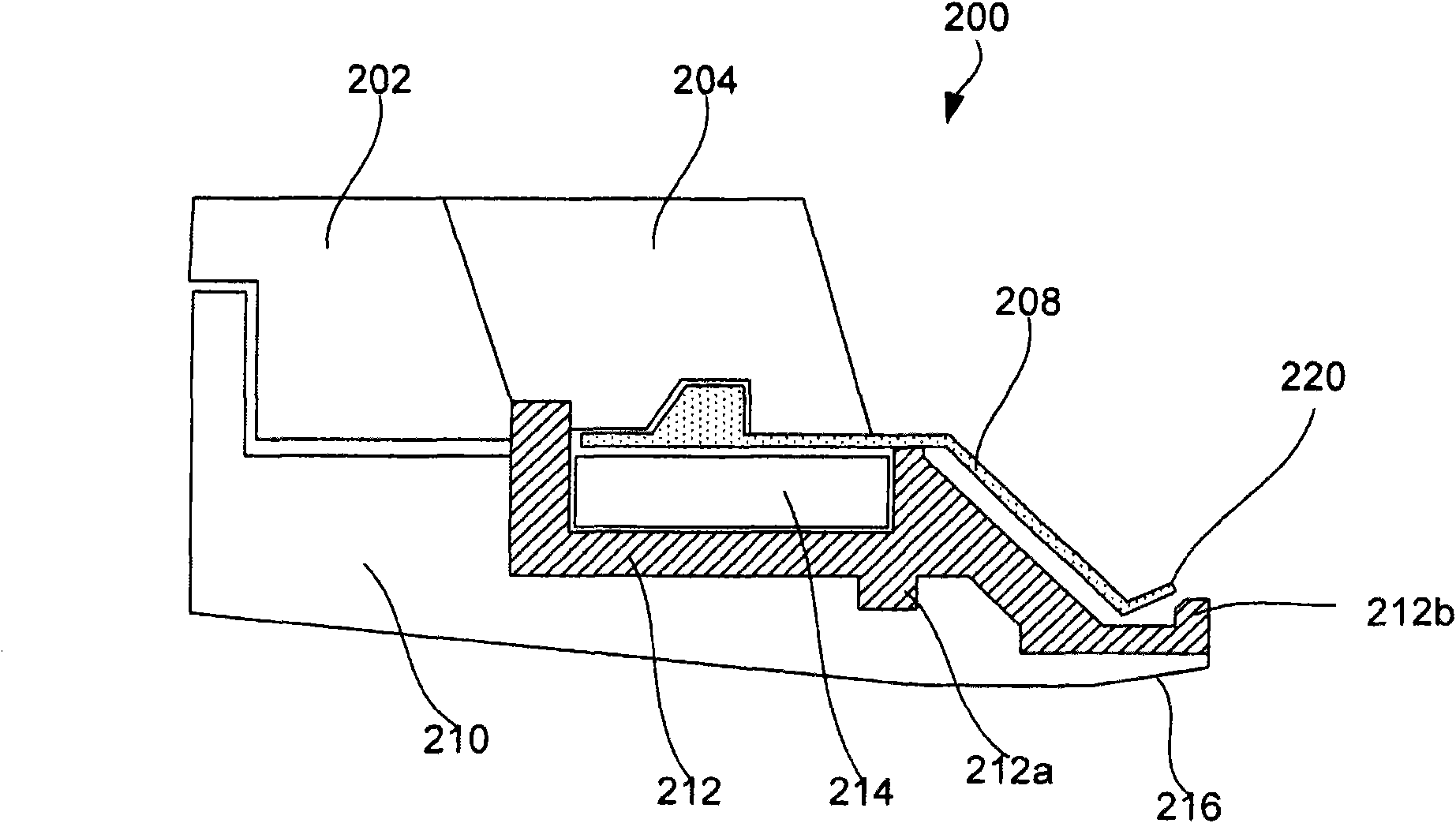
[0044] Electroplating and other processes using clamshells typically involve submerging at least a bottom portion of the clamshell in an electroplating solution. After plating is complete, the plated wafer is typically spun to remove most of the entrained concentrated electrolyte and rinsed with deionized water or another rinse liquid. The grab can then be spun again to remove residual rinse fluid (ie, the plating solution dilut...


PUM


Abstract

Methods, apparatuses, and various apparatus components, such as base plates, lipseals, and contact ring assemblies are provided for reducing contamination of the contact area in the apparatuses. Contamination may happen during removal of semiconductor wafers from apparatuses after the electroplating process. In certain embodiments, a base plate with a hydrophobic coating, such as polyamide-imide (PAI) and sometimes polytetrafluoroethylene (PTFE), are used. Further, contact tips of the contact ring assembly may be positioned further away from the sealing lip of the lipseal. In certain embodiments, a portion of the contact ring assembly and/or the lipseal also include hydrophobic coatings.

Description

[0001] Cross References to Related Applications [0002] This application is claimed under 35 U.S.C. § 119(e), which is hereby incorporated by reference in its entirety, filed on December 10, 2008, entitled "Wafer Electroplating Apparatus for Reducing Edge Defects ( WAFER ELECTROPLATING APPARATUS FOR REDUCING EDGE DEFECT S)” in U.S. Application No. 61 / 121,460. Background technique [0003] Electroplating, electroless plating, electropolishing, or other wet chemical deposition or removal processes used in semiconductor device fabrication can be performed in "grab bucket" equipment. Grabs (e.g. Novellus Systems (Novellus Systems) tool) are the "cup" and "cone" that form the assembly. In general, the cup and cone assembly holds, positions and often rotates the wafer during processing. A lip seal on the lip of the cup may contain embedded contacts for delivering plating current to the seed layer on the wafer. Grab buckets provide edge and backside protection to the wafer....

Claims


Application Information

Patent Timeline
IPC IPC(8): C25D17/06C25D17/00C25D19/00C25D7/12
CPCC25D17/001C25D7/123C25D7/12C25D17/004
Inventor 维奈·普拉巴卡布赖恩·L·巴卡柳古斯·加内桑珊迪纳斯·古奈加迪何志安史蒂文·T·迈尔罗伯特·拉什乔纳森·D·里德高田雄一詹姆斯·R·齐布里达
Owner NOVELLUS SYSTEMS
Why Eureka
Try Eureka