
Water flow measurement sensory control assembly

A technology of sensor control and water flow meter, which is applied in flow control of electric devices, volume measurement, liquid/fluid solid measurement, etc. It can solve problems such as multi-space, forced demolition cannot be monitored in time, and construction time is prolonged.

Inactive Publication Date: 2010-08-11
深圳市常工电子计算机有限公司
View PDF0 Cites 5 Cited by
  • Summary
  • Abstract
  • Description
  • Claims
  • Application Information

AI Technical Summary

Problems solved by technology

[0002] At present, the water meter or flow meter and the water switch controller are installed separately, and the water meter or flow meter is sealed by lead to prevent the user from forcibly dismantling and modifying; because separate installation will take up more space and increase the number of joints, resulting in waste of resources , which also lengthens the construction time; in addition, the traditional lead sealing method is used to prevent forced demolition from being monitored in time, which may cause waste of water

Method used


Image

  • Water flow measurement sensory control assembly
  • Water flow measurement sensory control assembly

Examples


specific Embodiment approach

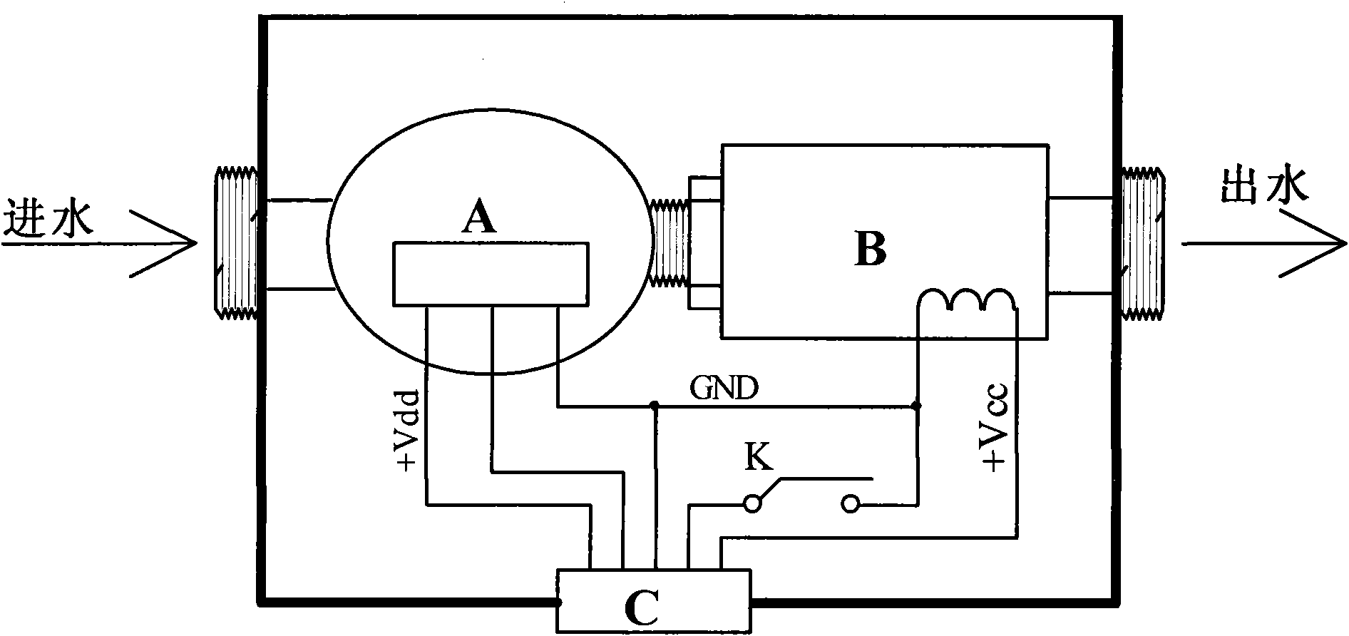
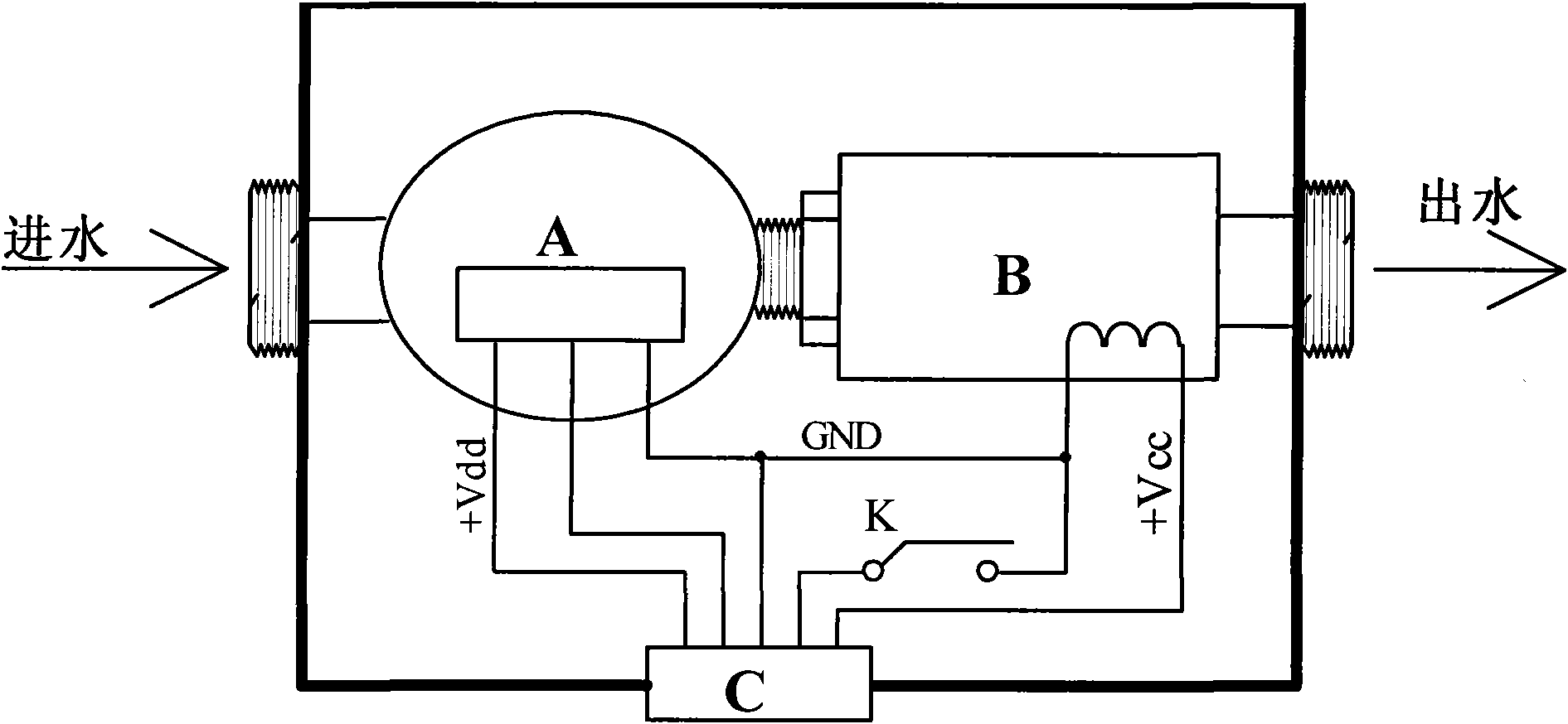
[0007] Specific implementation method: the water flow measurement sensor control assembly is to connect the electronic water flow meter A with the electronic control valve B, and put them into a casing together. The casing of the water flow measurement sensor control assembly is divided into an upper casing and an upper casing. There are two parts of the lower shell, fix an electronic button switch K on the lower shell with the button facing up, make a small pillar in the upper shell, the position and height of the pillar are: when the upper and lower shells are combined, the pillar should be pushed to On the button of the electronic button switch and make the electronic button switch just close; one contact of the electronic button switch K is connected to the ground wire of the electric control valve, and the other contact is connected to the power supply line and signal line of the electronic water flow meter and the electric control valve. The ground wires are uniformly twi...


PUM


Abstract

The invention discloses a water flow measurement sensory control assembly, which is characterized in that: the interior of the water flow measurement sensory control assembly consists of an electronic water flow meter, an electric control valve, a button switch and an intertwisted connecting line; the water outlet of the electronic water flow meter is connected with a water inlet of the electric control valve, then the electronic water flow meter and the electric control valve are put into a machine shell after being assembled together, the button switch is arranged in the machine shell and is closed when an upper shell and a lower shell of the machine shell are assembled in place, and one end of a leading-out wire of the button switch is communicated with a ground wire of the electric control valve while the other end of the leading-out wire of the button switch, a leading-out wire of the water flow meter and a leading-out wire of the electric control valve are connected to a connection port together; the water flow measurement sensory control assembly can be arranged through a waterway by only pressing a water inlet interface and a water outlet interface when the water flow measurement sensory control assembly is arranged at a user using site; and after the water flow measurement sensory control assembly is arranged, an intelligent water meter controller can detect the on-off status and the connecting status of the button switch and judge whether a user side has forced releasing and trimming abnormities while reading the electronic water flow meter and controlling the electric control valve.

Description

Technical field [0001] The invention is a control device for water flow measurement, which belongs to the field of measuring instruments. In particular, a water flow metering sensor control assembly that combines metering and control during waterway installation and has a forced demolition alarm function is synthesized. Background technique [0002] At present, the water meter or flow meter and the water switch controller are installed separately, and the water meter or flow meter is sealed by lead to prevent the user from forcibly dismantling and modifying; because separate installation will take up more space and increase the number of joints, resulting in waste of resources , It also lengthens the construction time; In addition, the traditional lead sealing method is used to prevent forced demolition from being monitored in time, which may cause waste of water. Contents of the invention [0003] In order to avoid saving resources, shorten construction time, and monitor...

Claims


Application Information

Patent Timeline
Patent Type & Authority Applications(China)
IPC IPC(8): G05D7/06G01F15/00G01F15/06
Inventor 江渊杨斌
Owner 深圳市常工电子计算机有限公司
Learn More