Method and device for controlling Hall sensor switch

A hall sensor and switch technology, applied in the field of sensor control, can solve the problems of contact ablation and mechanical wear of vehicle switches, and achieve the effects of avoiding mechanical wear, prolonging the service life and increasing the sensing distance

Inactive Publication Date: 2013-06-12
韩立东
View PDF8 Cites 3 Cited by
  • Summary
  • Abstract
  • Description
  • Claims
  • Application Information

AI Technical Summary

Benefits of technology

This patented device allows for precise detection of an object's location with improved precision compared to existing methods that require physical touches from outside devices like buttons or levers. It uses two different types of coils - one called a primary coil and another called a secondary coil – placed near each other at right angles to create a closed loop circuit containing both windings through them. By measuring changes caused by movement along these circuits, the sensor accurately measures its own displacement without physically moving parts inside their housing. Overall, this new system improves upon current technologies while providing greater flexibility in adjustable range and longer lifetimes over traditional systems.

Problems solved by technology

The technical problem addressed in this patents relates to improving the reliability and lifespan of electronic components within advanced vehicle systems like electric power steering system(EPS) due to their limited range of operation and potential damage caused during use. Current methods involve physical touch buttons attached to the circuit board itself, leading to reduced response speed and increased maintenance costs.

Method used


Image

  • Method and device for controlling Hall sensor switch
  • Method and device for controlling Hall sensor switch

Examples


Embodiment Construction

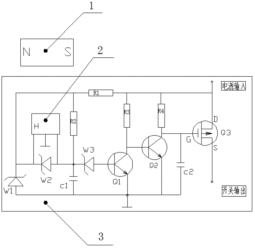
[0024] A control method of a Hall sensor switch: the distribution of the magnetic field strength around the permanent magnet is changed by changing the relative position of the external magnetic conductor (such as the shaft and gear of the car, etc.) and the permanent magnet, and the magnetic field around the permanent magnet is detected by the Hall element The change of the intensity and convert it into the change of the electrical signal; and the test shows that the conduction and shutdown of the Hall element also has the "Schmidt characteristic", that is, there is a positive threshold field strength and a negative threshold The field strength, and the lower the power supply voltage of the Hall element, the greater the sensing distance, and the greater the field strength difference between the positive threshold field strength and the negative threshold field strength, which means that the conduction of the Hall element The on-point and the off-point are not at the same point...


PUM


Abstract

The invention relates to a method and a device for controlling a Hall sensor switch, and belongs to the technical field of sensory control. The method comprises the following steps of: acquiring voltage U1 through a diode W1 and a resistor R1 when a Hall element is under an initial condition, wherein the Hall element is under a working condition when a magnetic conductor passes through a permanent magnet; acquiring voltage U2 through a diode W2 and the resistor R1, and converting detected magnetic field intensity change signals of the permanent magnet into electric signals which are transmitted to a circuit board by the Hall element; and outputting signal conversion switching signals transmitted by the Hall element through a connecting socket by the circuit board. The device comprises the permanent magnet and the like, wherein the permanent magnet, the Hall element and the circuit board are arranged inside an outer housing; the Hall element is connected with the circuit board; the circuit board is connected with the connecting socket; one end of a radiator is connected with the circuit board, and the other end of the radiator is earthed; and a sealing ring is arranged between the connecting socket and the outer housing. The invention discloses the method for controlling the Hall sensor switch so as to achieve the purpose of accurate sensing. The problems of pitting of contact and mechanical wear of a vehicle switch are solved, and the service life of the vehicle switch is prolonged.

Description


Claims


Application Information

Patent Timeline
Owner 韩立东
Why Eureka
Try Eureka