Rotary type push switch

A rotary and switch technology, which is applied in the direction of electric switches, building structure supports, electrical components, etc., can solve the problems of inability to ensure stable contacts, easy wear of contact protrusions, and inability to ensure contact performance, etc., to achieve excellent contact Point performance, excellent operation feeling, and the effect of mass production

Active Publication Date: 2012-11-07
KAMADA KOREA
View PDF5 Cites 1 Cited by
  • Summary
  • Abstract
  • Description
  • Claims
  • Application Information

AI Technical Summary

Problems solved by technology

[0010] However, in the above-mentioned existing rotary push switch, the contact mode is completed by pressurized contact of the contact protrusion of the movable terminal. The protruding part is easy to wear, resulting in poor contact contact and shortening the life of the switch
[0011] In particular, since the above-mentioned movable terminal is formed in the shape of an integral disc, stable contact cannot be ensured if deformation such as twisting occurs.
[0012] In addition, since the coupling between the above-mentioned shaft and the moving terminal is assembled by insertion, the contact part may come off due to misalignment between the shaft and the moving terminal, and correct contact performance cannot be ensured.
[0013] In addition, in the existing rotary push switch, lubricating oil is applied to the contact part during production, so the process is increased, and the surroundings of the components become messy due to the application of lubricating oil

Method used


Image

  • Rotary type push switch
  • Rotary type push switch
  • Rotary type push switch

Examples


Embodiment Construction

[0041] Hereinafter, preferred embodiments of the present invention will be described in detail with reference to the accompanying drawings.

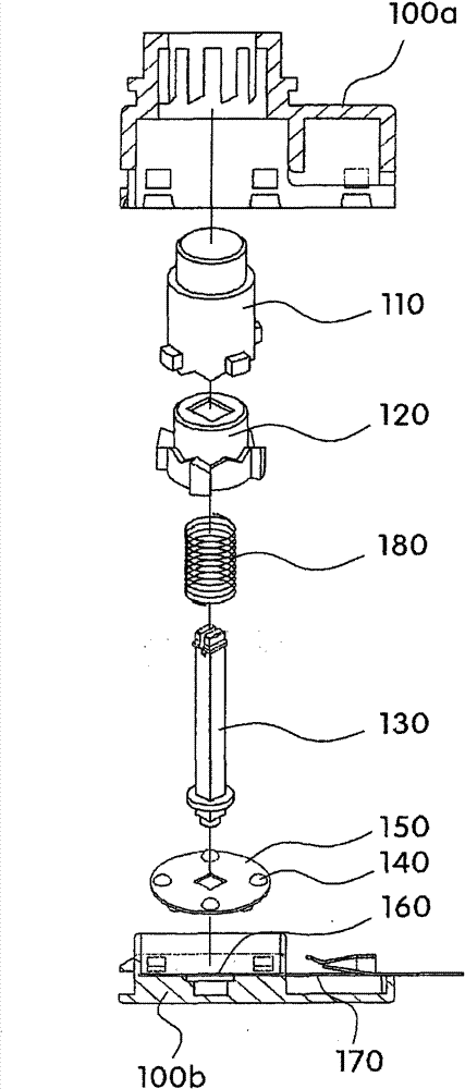
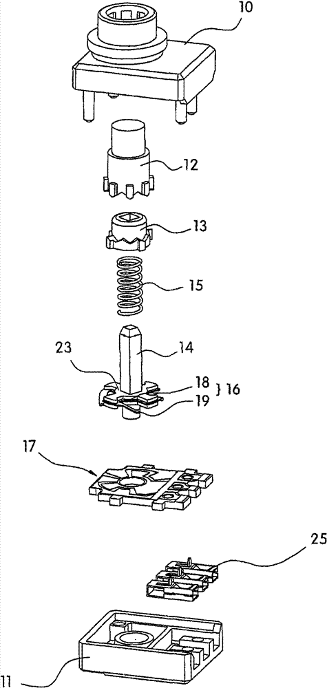
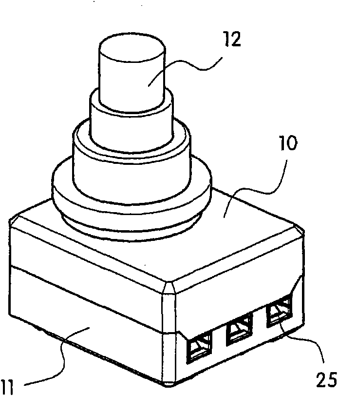
[0042] figure 2 , Figure 3a and Figure 3b It is a schematic diagram of a rotary push switch according to an embodiment of the present invention.

[0043] Such as figure 2 , Figure 3a and Figure 3b As shown, the above-mentioned rotary push switch includes: upper / lower shells 10, 11, which accommodate other components by assembling up and down; button 12, as a component contained in the above-mentioned upper shell 10, for the user to complete the operation; The tube 13 completes the cam action through the operation of the above-mentioned button 12; the movable terminal 16 and the shaft 14 rotate intermittently through the operation of the above-mentioned solenoid 13 and forms a contact with the fixed terminal 17; the spring 15 is used to restore the above-mentioned button 12; and The fixed terminal 17 is a component accommodate...


PUM


Abstract

The present invention relates to a rotary type push switch which is mainly used for one-touch ON / OFF automobile indoor lamps and the like. The rotary type push switch provided by the present invention, in order to ensure the stable electricity performance of the switch, uses tension of a mobile terminal to form contacts so that the mobile terminal is integrally inserted into a shaft, and uses a four-contact form and forms an electrical pattern by a PCB substrate to remove a coating technology of lubricating oil when manufacturing the switch. The rotary type push switch of the present invention is featured with excellent switch operation, further prolongs the service life, prevents the terminal from separating and deforming, simultaneously, keeps and supports the tension of the terminal, and exerts excellent performance of the contacts. The electric planeness and the position of the pattern are even, and the coating layer is formed by contact faces, the stable electricity performance is kept. Furthermore, because two contacts form an integral rough point, even one of them loses the function, the other one can also keep the electricity performance; and the step is simplified and thevolume production is realized by removing the coating technology of lubricating oil when manufacturing the switch.

Description

technical field [0001] The present invention relates to a rotary type push switch (Rotary type push switch), especially a rotary type push switch mainly used for a one-touch ON / OFF type of an automobile interior lamp or the like. Background technique [0002] Generally speaking, the rotary push switch is a switch suitable for low-voltage circuits such as automotive circuits, and is mainly used to adjust the work of automotive interior lights such as overhead lights, map lights, or other auxiliary lights. [0003] The above-mentioned switch makes the electric contact part continuously generate the continuous operation of the button of the constraint through the rotary switch device, and makes the circuit work and release sequentially. [0004] For example, the above-mentioned rotary push switch is a switch that will complete the ON / OFF action in sequence if the button is pressed repeatedly. [0005] The above-mentioned rotary push switch includes buttons, springs, solenoids,...

Claims


Application Information

Patent Timeline
Patent Type & Authority Patents(China)
IPC IPC(8): H01H25/00H01H1/06
CPCE04G5/14E04G21/3228F16B2/12
Inventor 崔炳喆
Owner KAMADA KOREA
Why Eureka
Try Eureka