
Equipment detection method and equipment

An equipment detection and equipment technology, applied in the field of communication, can solve the problems of broken pins of the interface board and the main control board, loss of manpower and material resources for troubleshooting, and the cause of the failure is not easily exposed, etc., and achieves the effect of saving manpower and material resources.

Active Publication Date: 2010-08-11
NEW H3C TECH CO LTD
View PDF5 Cites 10 Cited by
  • Summary
  • Abstract
  • Description
  • Claims
  • Application Information

AI Technical Summary

Problems solved by technology

[0012] However, the power-on self-test process of the above-mentioned equipment is only for the self-test inside the chip, and does not involve the detection of the connecting lines between the chips and the boards.
However, during the actual operation and testing of the equipment, communication problems often occur due to virtual plugging between the interface board and the main control board, or some pins are broken.
Moreover, the causes of failures caused by these problems are not easy to be exposed in many cases, which brings a great loss of manpower and material resources to troubleshooting

Method used


Image

  • Equipment detection method and equipment
  • Equipment detection method and equipment
  • Equipment detection method and equipment

Examples


Embodiment Construction

[0046] The core idea of ​​the present invention is: configure the detection message to perform hardware detection on the control level, data level and detection level of the device, so as to ensure that the connection between the main control board and the interface board of the device is normally connected.

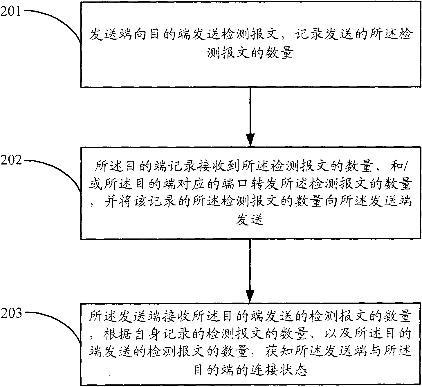
[0047] The invention provides a device detection method, which is applied to a device including a main control board and an interface board. Check the connection status of the software, such as figure 2 As shown, the method further includes:

[0048] Step 201, the sending end sends detection packets to the destination end, and records the number of detection packets sent;

[0049] Step 202, the destination end records the number of detection packets received and / or the number of detection packets forwarded by the port corresponding to the destination end, and sends the recorded number of detection packets to The sending end sends;

[0050]Step 203, the sending end re...


PUM


Abstract

The invention discloses an equipment detection method and equipment. Hardware detection is performed on a control layer, a data layer and a detection layer of the equipment by configuring detection message to ensure normal connection of a connector between a main control board and an interface board of the equipment; and when the connection is abnormal, the abnormality is reported in time so as to save a large amount of human and material resources.

Description

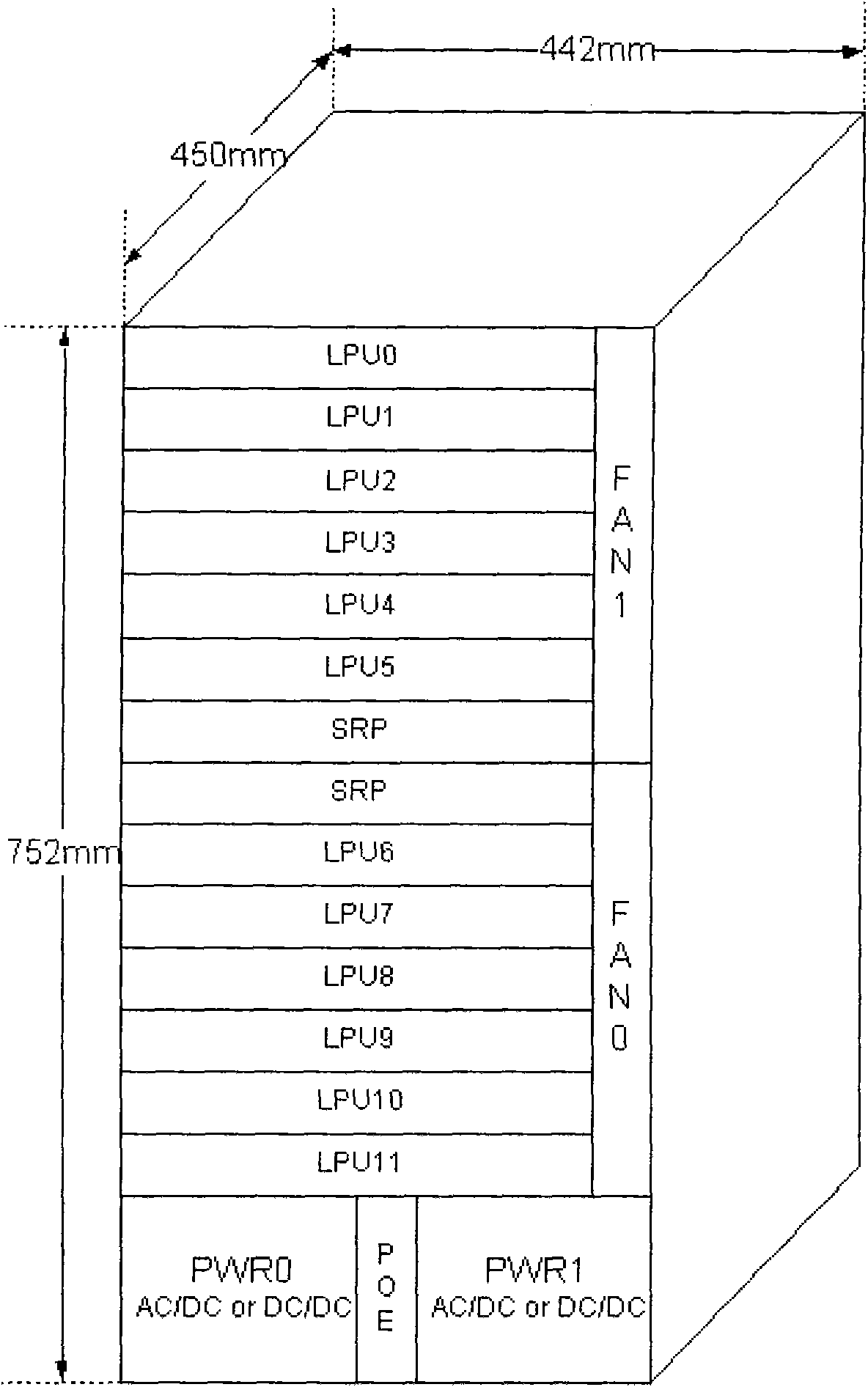
technical field [0001] The present invention relates to the communication field, in particular to a device detection method and device. Background technique [0002] At present, many high-end devices have an integrated frame structure, and the main control board and interface board are connected in the frame structure by plugging. Such as figure 1 As shown, each LPU represents an interface board, and SRP represents the main control board. Both the interface board and the main control board can be manually plugged. Since the interface board and the main control board are connected by pins, there may be some problems during use, such as false insertion or damage to the pins caused by improper use. [0003] In the prior art, after the equipment is powered on, a self-check process is usually configured. The self-check process mainly includes hardware self-check and data verification during the startup process. The self-check method includes: [0004] Memory self-test: [000...

Claims


Application Information

Patent Timeline
Patent Type & Authority Applications(China)
IPC IPC(8): H04L12/26H04L12/56
Inventor 王茹萍王伟
Owner NEW H3C TECH CO LTD
Learn More