
Phase error detection with conditional probabilities

A technology of phase error and conditional probability, applied in the field of communication

Inactive Publication Date: 2013-03-27
INTEL CORP
View PDF4 Cites 1 Cited by
  • Summary
  • Abstract
  • Description
  • Claims
  • Application Information

AI Technical Summary

Problems solved by technology

For example, in some systems the received signal level may vary by more than 90dB

Method used


Image

  • Phase error detection with conditional probabilities
  • Phase error detection with conditional probabilities
  • Phase error detection with conditional probabilities

Examples


Embodiment Construction

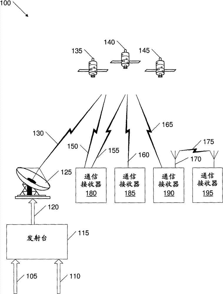
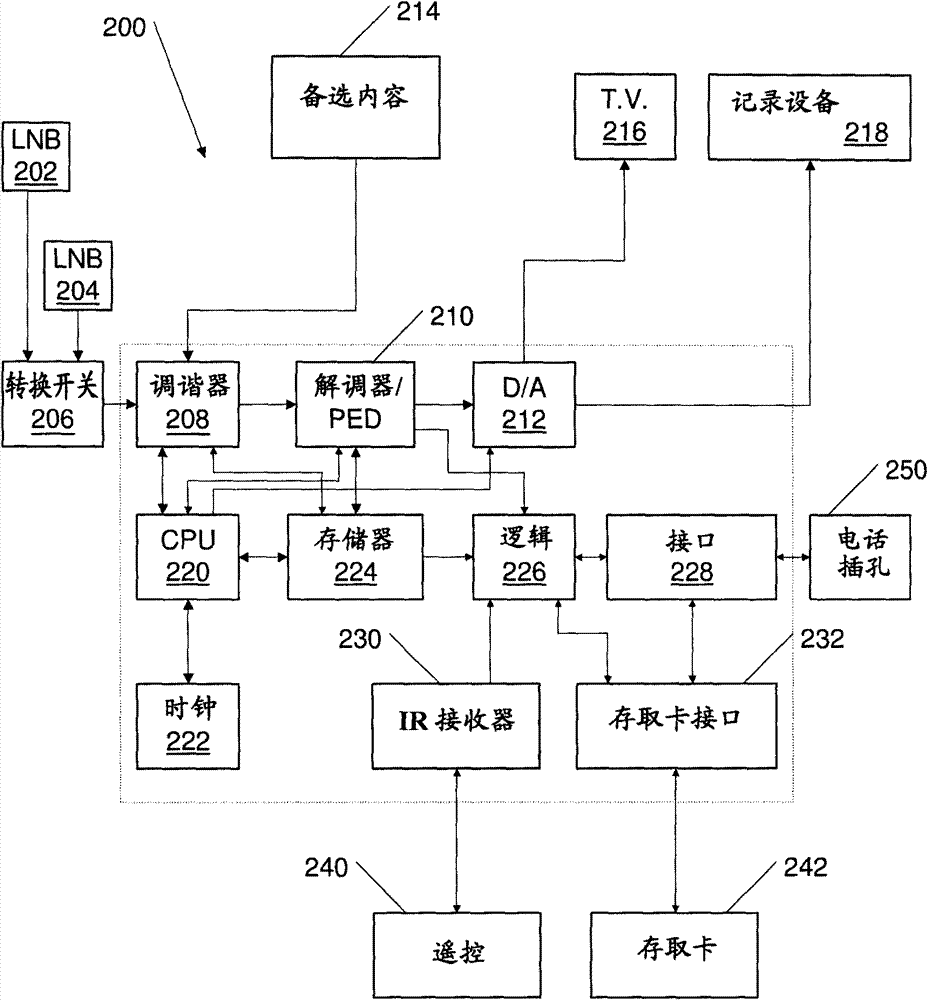
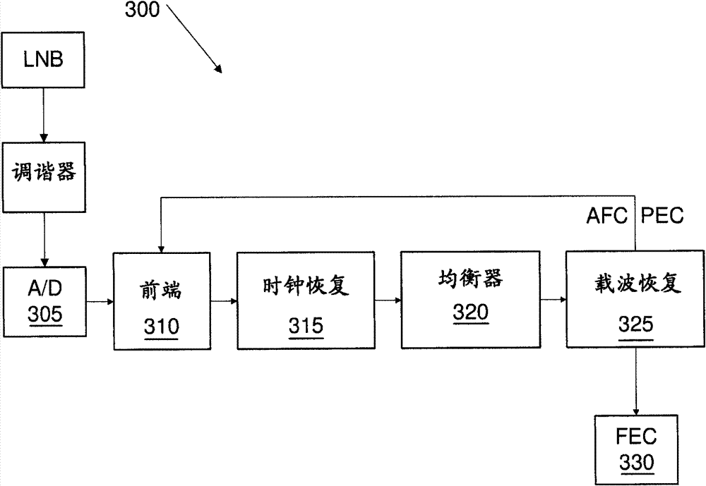
[0018] The following is a detailed description of the embodiments shown in the drawings. The description has been in such detail that these embodiments are clearly conveyed. However, the amount of detail provided is not intended to limit anticipated variations of the embodiments. On the contrary, the intention is to cover all modifications, equivalents and alternatives falling within the spirit and scope of the embodiments as defined by the appended claims.

[0019] In general, apparatus, systems, methods, and computer program products stored in tangible media are contemplated that employ conditional probabilities to calculate phase errors. For a received signal, an embodiment may form several phase error estimates associated with each point of the constellation, the number and location of which depends on the modulation technique of the received signal. In addition to calculating phase error estimates, these embodiments may also calculate weights or probabilities associated...


PUM


Abstract

Apparatuses, systems, and methods that employ conditional probabilities to calculate phase errors are disclosed. For a received signal, the embodiments may develop several phase error estimates relative to each point of a constellation, the number and location of points of the constellation depending on the modulation technique of the received signal. In addition to calculating the phase error estimates, the embodiments may also calculate weights, or probabilities, associated with each of the estimates. The embodiments may use the estimates and the weights to calculate a composite phase error estimate. The composite phase error estimate may be used to correct the received signal and eliminate or reduce the impact of the phase error.

Description

technical field [0001] The embodiments herein belong to the field of communications. More specifically, these embodiments relate to methods and apparatus for detecting phase errors for a communication receiving device via conditional probability. Background technique [0002] In a typical radio frequency (RF) communication system, data may be processed at a transmitter device, modulated, filtered, amplified, and transmitted to one or more receiver devices. Typically, a transmitted signal experiences path loss, multipath interference, and other types of signal degradation before reaching a receiver device. A receiver device receives the modulated signal, performs various types of conditioning, and demodulates the conditioned signal to recover the transmitted data. Signal conditioning typically includes low noise amplification, filtering, automatic gain control, frequency down conversion, sampling, quantization, and the like. [0003] Modern communication systems use a vari...

Claims


Application Information

Patent Timeline
Patent Type & Authority Patents(China)
IPC IPC(8): H04L27/22H04B17/00
CPCH04L2027/0057H04L2027/0036H04L27/2273H04L2027/0067H04L27/3827H04L2027/003H04L2027/0038H04L2027/0069H04B1/10H04B7/185H04L27/18
Inventor T·赫瓦维塔纳B·阿拉姆贝波拉P·舒克拉S·加米奇V·布恩君
Owner INTEL CORP
Learn More