Tape feeder

A technology of feeder and top belt, which is applied in the field of belt feeder and can solve the problem of not being able to prevent parts from flying out

Active Publication Date: 2010-08-11
FUJI MASCH MFG CO LTD
View PDF1 Cites 10 Cited by
  • Summary
  • Abstract
  • Description
  • Claims
  • Application Information

AI Technical Summary

Problems solved by technology

[0007] However, in this structure, even if the length of the short tape is longer than that of the tape cover, since the entire top tape is peeled off from the short tape, there i...

Method used


Image

  • Tape feeder
  • Tape feeder
  • Tape feeder

Examples


Embodiment Construction

[0022] Hereinafter, an example which actualizes the preferred mode for carrying out the present invention will be described.

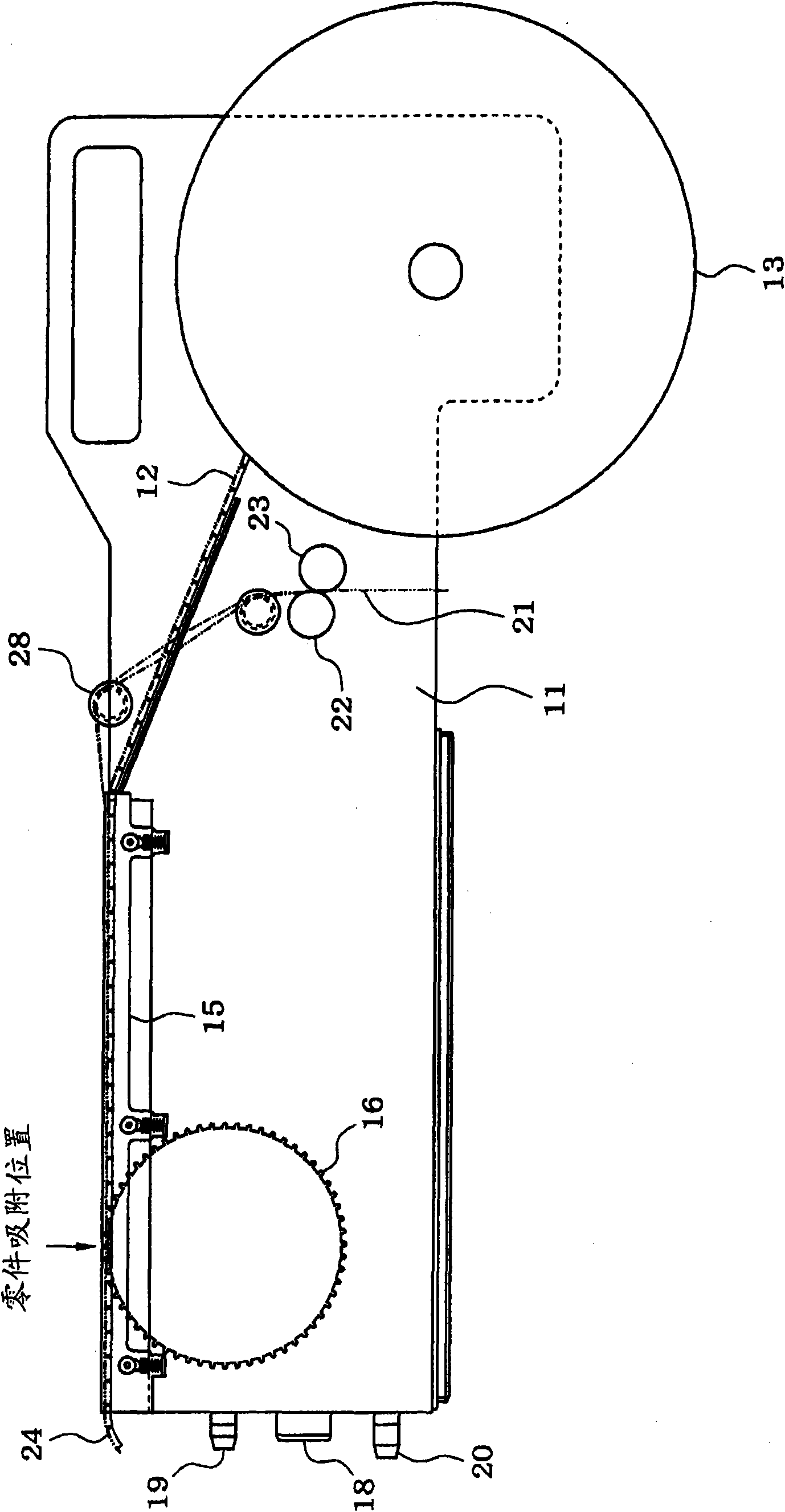
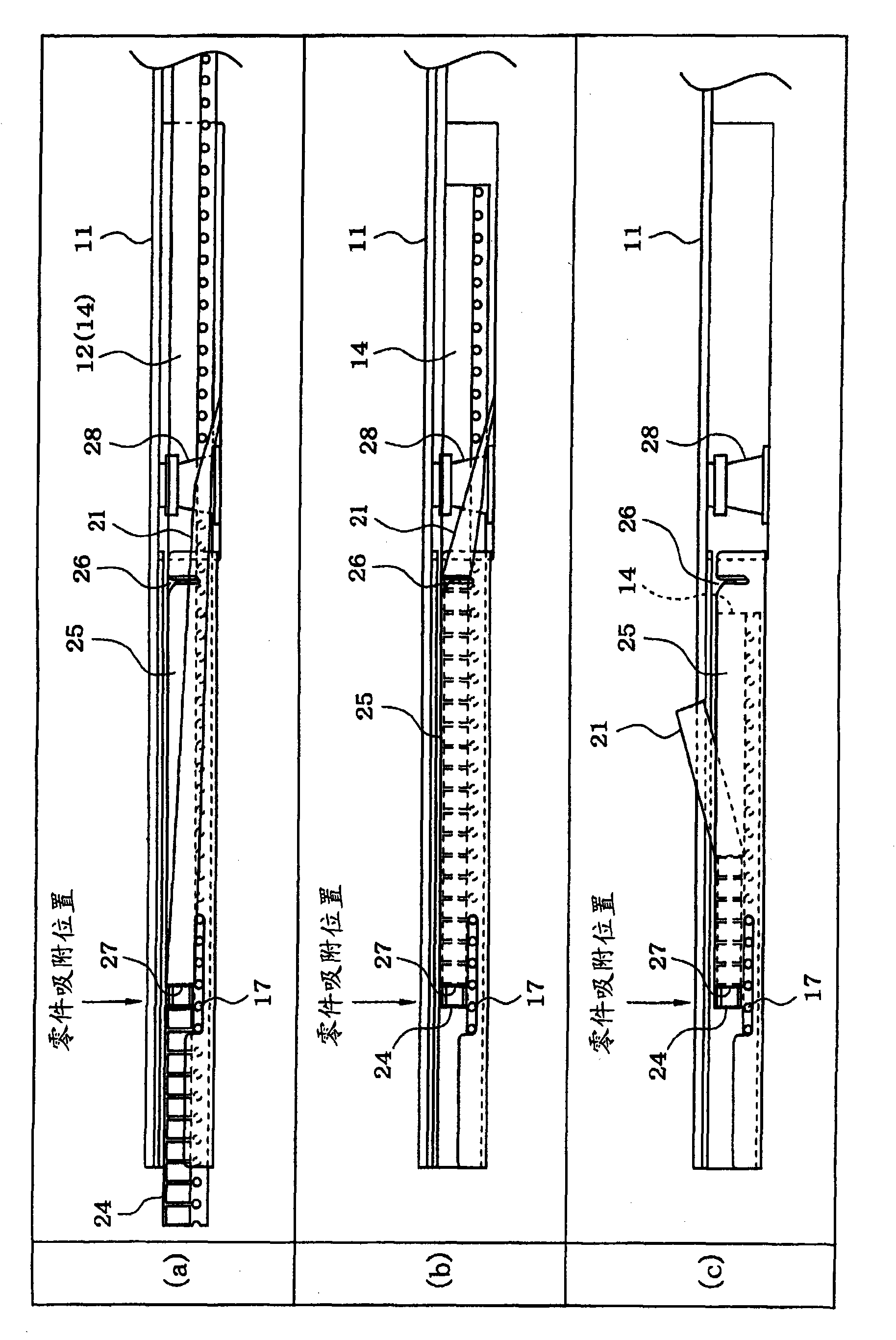
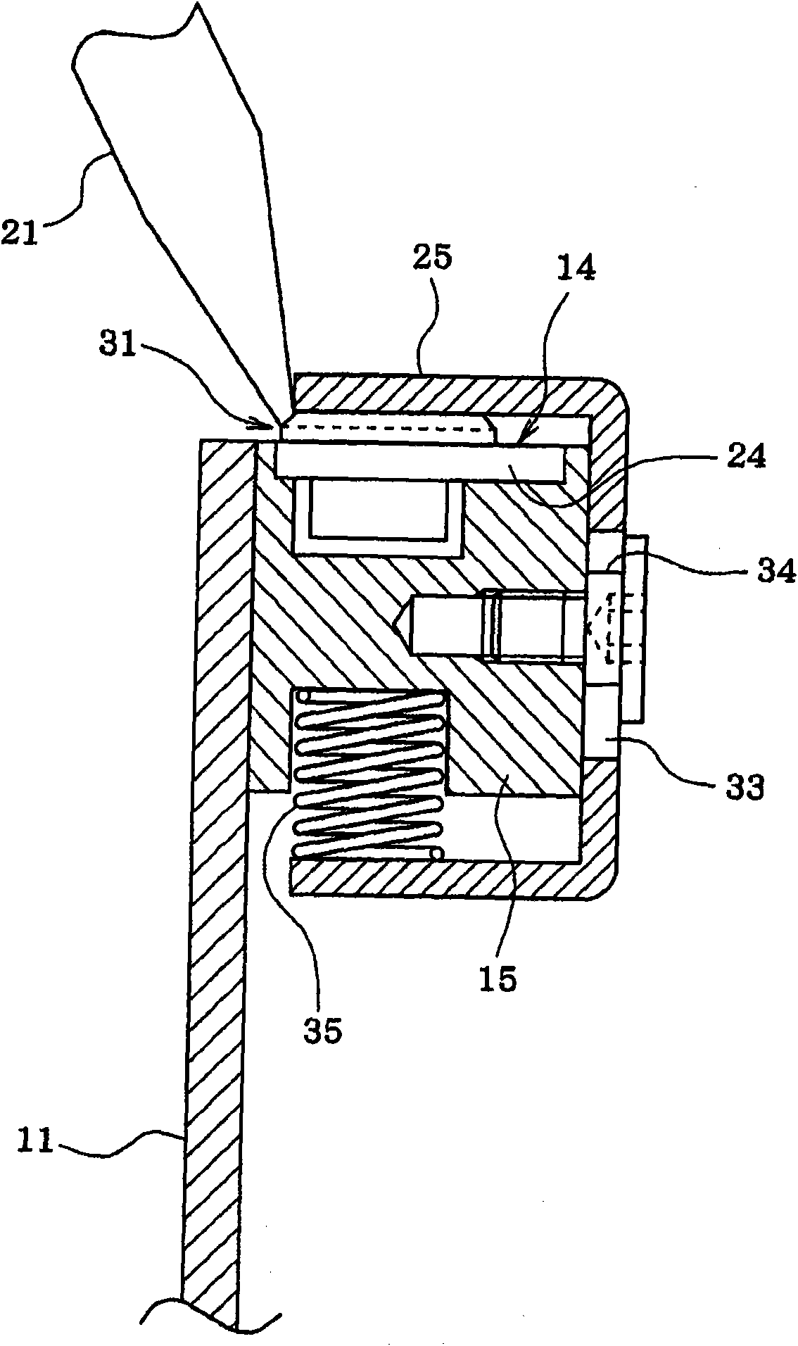
[0023] First, based on Figure 1 to Figure 3 The structure of the tape feeder will be described.

[0024] On the front end side of the feeder body 11 of the tape feeder ( figure 1 In the right side of the figure), a tape roll 13 around which the parts packaging tape 12 is wound is detachably provided. When using the short tape 14 (parts packaging tape after cutting), it is used in a state where the tape roll 13 is removed from the feeder main body 11 .

[0025] Attached to the upper surface of the feeder body 11 is a tape guide member 15 forming a tape path for guiding the parts packaging tape 12 or the short tape 14 pulled out from the tape roll 13 to the parts suction position. Inside the feeder body 11 ( figure 1 The left side in the middle), a toothed reel 16 (stepping conveying mechanism part) for stepping and conveying the parts packaging bel...


PUM


Abstract

The length of the tape path from a first top tape peeling-off section (26) to a second top tape peeling-off section (27) (part adsorption position) is made to be longer than the length of the tape path from the first top tape peeling-off section (26) to a tape delivery roller. In case that a strip tape (14) longer than a tape cover (25) is used, when the front end of the strip tape (14) is set at the part adsorption position and a top tape (21) is peeled from the front end of the strip tape (14) to the first top tape peeling-off section part (26), the peeled length of the top tape (21) becomes longer than the length of the tape path from the first top tape peeling-off section (26) to the top tape feed roller, whereby the front end of the top tape (21) can be set to the top tape feed roller.

Description

technical field [0001] The present invention relates to a tape feeder for stepwise conveying a parts packaging tape containing parts at predetermined intervals to a parts adsorption position. Background technique [0002] Usually, a parts packing tape is formed by adhering a top tape to the upper surface of a carrier tape on which parts are accommodated at fixed pitches, wound around a tape roll, and set on a tape feeder. The tape feeder pulls out the parts packing tape from the tape roller, and peels off the top tape from the parts packing tape through the top tape peeling part provided on the part immediately before the part suction position, so that the parts in the carrier tape are exposed and released to the parts. The suction position is conveyed step by step, and the top tape peeled off from the part packaging tape is pulled out along the direction opposite to the step conveying direction of the part packaging tape, and sent out by the top tape sending mechanism. [...

Claims


Application Information

Patent Timeline
IPC IPC(8): H05K13/02
CPCH05K13/0417H05K13/0419
Inventor 胜见裕司高田幸则
Owner FUJI MASCH MFG CO LTD
Why Eureka
Try Eureka