
High-voltage spiral tube type heat exchanger distributing device

A technology of coiled tube heat exchanger and distribution device, which is applied in the direction of heat exchanger shell, heat exchange equipment, lighting and heating equipment, etc. problem, to achieve the effect of stiffness enhancement

Inactive Publication Date: 2010-08-18
KAIFENG AIR SEPARATION GROUP
View PDF8 Cites 0 Cited by
  • Summary
  • Abstract
  • Description
  • Claims
  • Application Information

AI Technical Summary

Problems solved by technology

As a result, the strength of the entire heat exchange equipment cannot meet the requirements of use, the entire tube bundle sinks during operation, the heat transfer capacity between the media is greatly reduced, and the resistance is also increased accordingly, resulting in the failure of the entire equipment to operate normally.
This is also a design difficulty that has plagued large coiled tube heat exchangers for a long time

Method used


Image

  • High-voltage spiral tube type heat exchanger distributing device
  • High-voltage spiral tube type heat exchanger distributing device

Examples


Embodiment Construction

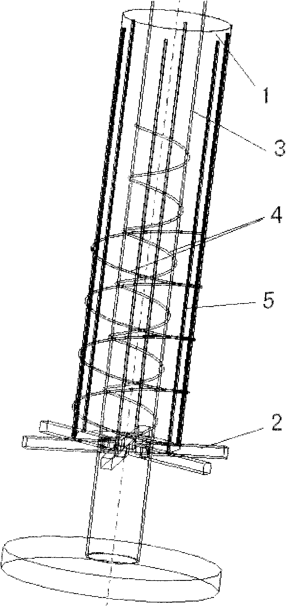
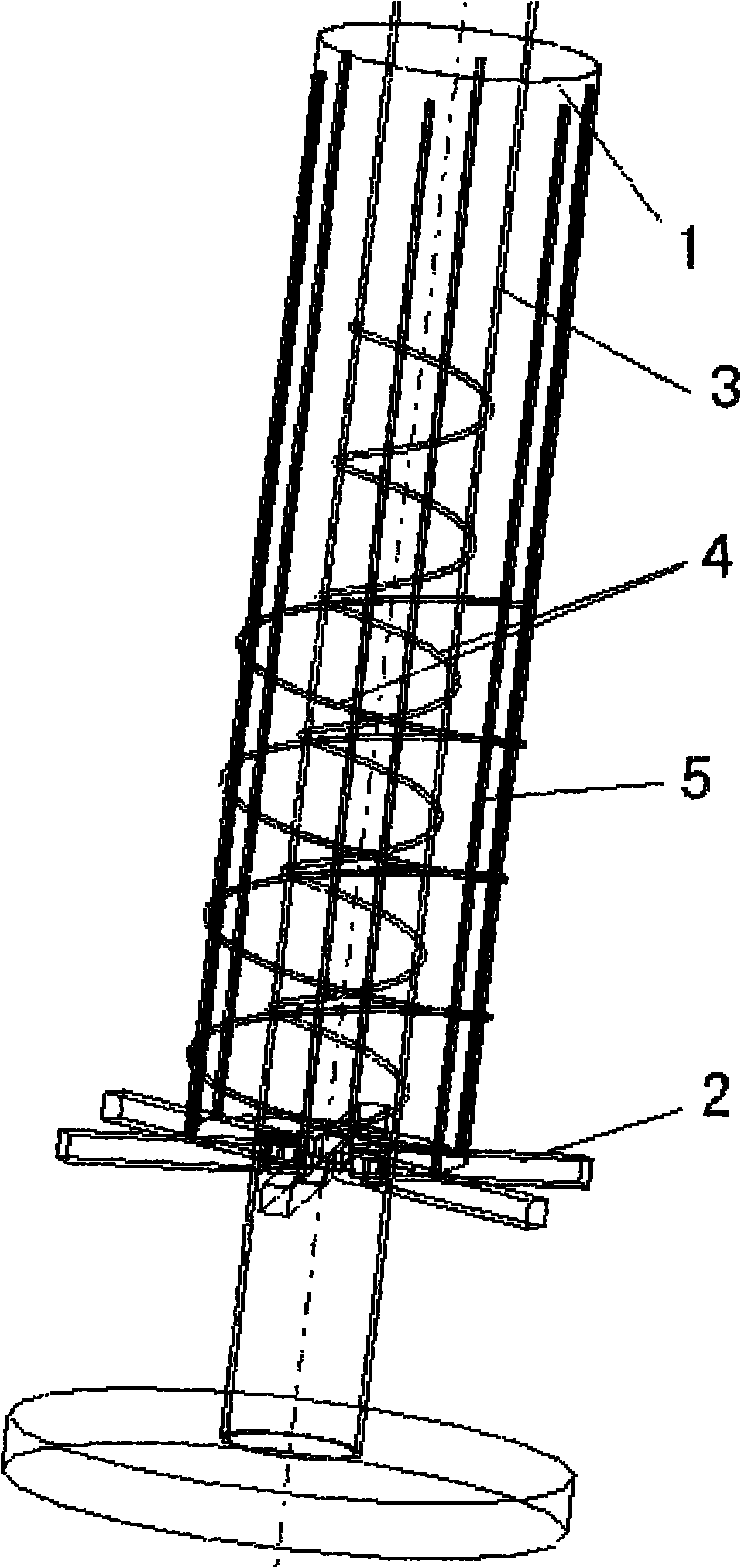
[0015] Such as figure 1 As shown, a high-pressure wound tube heat exchanger distribution device includes a load spreading cylinder 1 arranged in the heat exchanger, which is characterized by:

[0016] A star-shaped support 2 is fixedly installed on the lower bottom of the load spreading cylinder 1, a special-shaped cushion strip 5 is arranged on the outer surface of the load spreading cylinder 1, and a special-shaped cushion strip 5 is spirally arranged along the outer surface of the load spreading cylinder 1. Spiral heat exchange tube 4;

[0017] A central tube 3 is installed in the load spreading tube 1, a special-shaped cushion strip 5 is also arranged on the outer surface of the central tube 3, and a spiral heat exchange tube 4 is also spirally arranged on the special-shaped spacer 5 along the outer surface of the central tube 3 ;

[0018] Holes are evenly distributed on the surface of the load spreading cylinder 1.

[0019] The openings uniformly distributed on the surface of t...


PUM

PropertyMeasurementUnit
Apertureaaaaaaaaaa
Pitchaaaaaaaaaa

Abstract

The invention relates to a load distributing device used on heat exchange equipment, in particular to a high-voltage spiral tube type heat exchanger distributing device comprising a load distributing barrel arranged in a heat exchanger, a star-shaped support is fixedly installed on the lower bottom of the load distributing barrel, heterogenic butt strips are arranged on the outer surface of the load distributing barrel, and spiral heat exchange pipes are spirally arranged on the heterogenic butt strips along the outer surface of the load distributing barrel; a central barrel is installed in the load distributing barrel, the heterogenic butt strips are also arranged on the outer surface of the central barrel, and the spiral heat exchange pipes are also spirally arranged on the heterogenic butt strips along the outer surface of the central barrel; and openings are uniformly distributed on the surface of the load distributing barrel. The load distributing barrel, the star-shaped support and the heterogenic butt strips, which are arranged in the invention, are welded into a whole so that the integral strength and rigidity of the invention are greatly enhanced, and therefore, the design and the manufacture of a large-scale spiral tube type heat exchanger are realized; and the invention has the advantages of simple structure, convenient use and uniform load distribution.

Description

Technical field [0001] The invention relates to a load distribution device used on heat exchange equipment, in particular to a high-pressure pipe-wound heat exchanger distribution device. Background technique [0002] Generally, the medium channels on the high-pressure wound tube heat exchange equipment are alternately wound in different spiral directions. Since there are many layers of large-scale equipment, reaching more than one hundred layers, the load increases with the number of layers, especially the greater the stress formed by the outer layer load. As a result, the strength of the entire heat exchange equipment cannot meet the requirements of use, the entire tube bundle sinks during operation, the heat transfer capacity between the media is greatly reduced, and the resistance increases accordingly, causing the entire equipment to fail to operate normally. This is also a design difficulty that has long plagued large-scale wound tube heat exchangers. Summary of the inven...

Claims


Application Information

Patent Timeline
IPC IPC(8): F28F9/00
Inventor 牛玉振
Owner KAIFENG AIR SEPARATION GROUP
Learn More