Electronic switch operation anti-jumping circuit

A switch operation and anti-jumping technology, which is applied in the direction of panel/switch station circuit devices, etc., can solve the problems of poor versatility, different coil internal resistance, and large difference in starting current.

Inactive Publication Date: 2010-08-18
咸阳供电局 +1
View PDF5 Cites 3 Cited by
  • Summary
  • Abstract
  • Description
  • Claims
  • Application Information

AI Technical Summary

Problems solved by technology

[0004] Since there are many manufacturers of switch cabinets, their arc extinguishing principles, operating mechanisms and control circuits are different, and the working currents of the coils required for closing and opening operations are different, that is, the internal resistances of the coils are different, so that the coils connected in series The starting current required for the current coil of the anti-jump relay to work is very different. Different switch cabinets need to match the anti-jump relay of different specifications, and this kind of anti-jump relay that works at high voltage and high current is very bulky and is not suitable for use. Design the anti-jump function inside the microcomputer protection device
At the same time, the traditional anti-jump circuit design needs to use different relays for the design of the AC circuit and the DC circuit, and the versatility is not good.

Method used


Image

  • Electronic switch operation anti-jumping circuit
  • Electronic switch operation anti-jumping circuit
  • Electronic switch operation anti-jumping circuit

Examples


Embodiment Construction

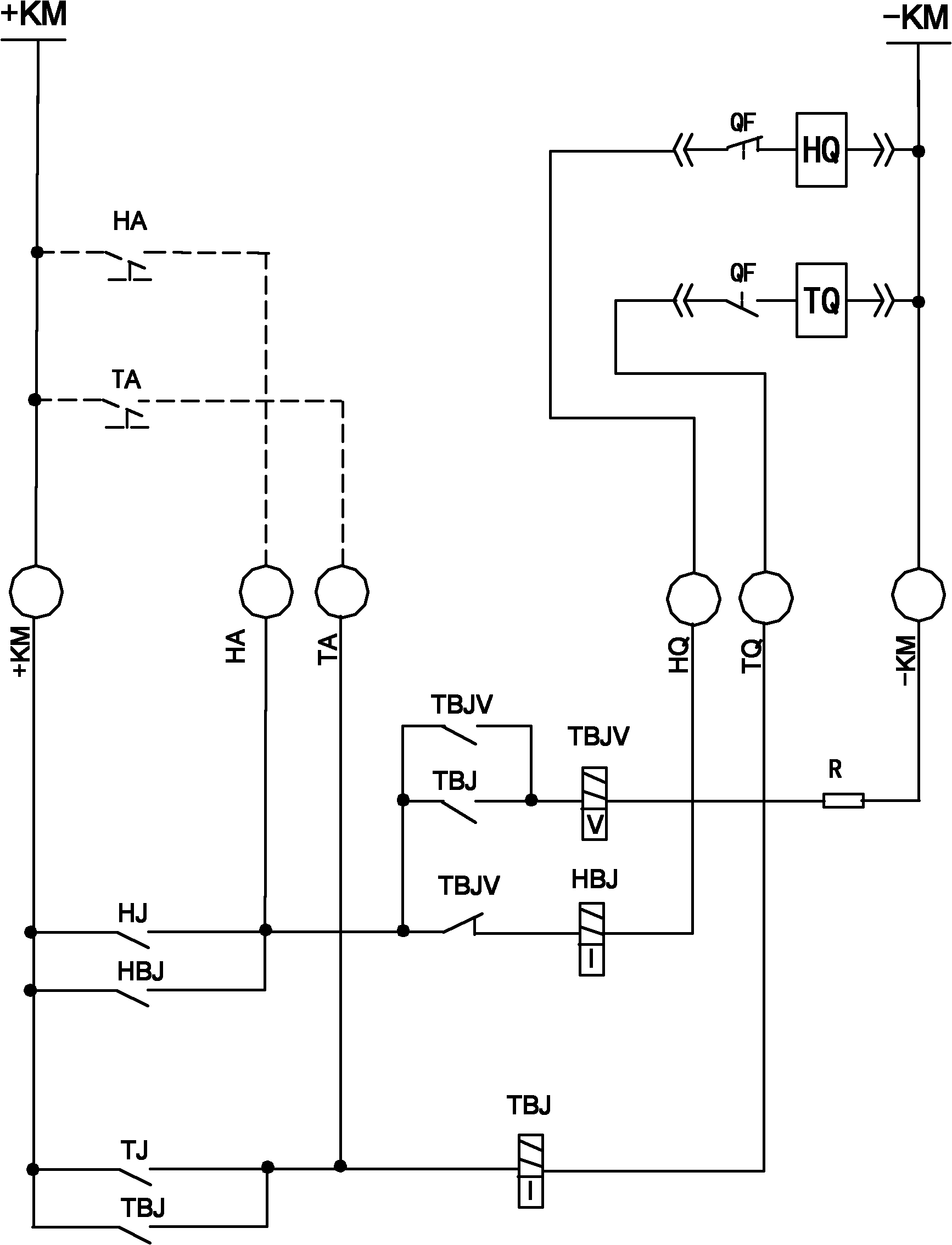
[0015] refer to figure 1 , In the switch operation anti-jump circuit, +KM and -KM are the positive and negative poles of the control power supply respectively, the HA and HQ nodes are the access points of the closing intermediate relay HBJ, and the TA and TQ nodes are the access points of the opening intermediate relay TBJ . The opening control circuit is sequentially connected in series between the positive and negative poles +KM and -KM of the control power supply, and consists of the opening button TA, the TA node, the coil of the opening intermediate relay TBJ, the TQ node, and the opening coil TQ. The closing control loop is composed of the closing button HA, the HA node, a group of normally closed contacts of the auxiliary intermediate relay TBJV, the coil of the closing intermediate relay HBJ, and the closing coil HQ. A group of normally open contacts of the opening intermediate relay TBJ, the coil of the auxiliary intermediate relay TBJV and matching resistor R are co...


PUM


Abstract

The invention discloses an electronic switch operation anti-jumping circuit. The circuit comprises a control power supply, a switching-on intermediate relay, a switching-off intermediate relay, an auxiliary intermediate relay, switching-on coils, switching-off coils, a switching-on button, and a switching-off button. The switching-off control loop consisting of the switching-off button, the coils of the switching-off intermediate relay and the switching-off coils, and a switching-on control loop consisting of the switching-on button, a set of normally closed contacts of the auxiliary intermediate relay, the coils of the switching-on intermediate relay and the switching-on coils are successively connected in series between the positive and negative electrodes of the control power supply; another electric node of the switching-on button is HA, a set of normally open contacts of the switching-off intermediate relay and the coils of the auxiliary intermediate relay are successively connected in series between the HA and the negative electrode of the control power supply, and the two ends of the normally open contacts of the switching-off intermediate relay are in parallel connection with the normally open contacts of the auxiliary intermediate relay; and two ends of the coils of the switching-on intermediate relay and the switching-off intermediate relay are respectively in parallel connection with clamp diode groups.

Description

technical field [0001] The invention relates to a secondary control circuit of a high-voltage switch cabinet, in particular to an electronic switch operation anti-jump circuit. Background technique [0002] The anti-jump function in the control circuit of the high-voltage switchgear means that when the closing circuit breaks down, the closing contact of the control switch or the automatic device fails to return in time (for example, the operator does not release the handle, and the closing contact of the automatic device fails to return in time). Gate contact adhesion) leads to closing, and at this time because the short circuit accident has not been ruled out, there will be a phenomenon of circuit breaker reciprocal compound opening. This phenomenon not only easily causes or expands accidents, but also causes equipment damage or personal accidents. [0003] The traditional electrical anti-jump circuit generally adopts the double-coil electromagnetic relay mode of current s...

Claims


Application Information

Patent Timeline
IPC IPC(8): H02B1/24
Inventor 贠维徐宏康鹏程晓瑞李鹏李斌
Owner 咸阳供电局
Why Eureka
Try Eureka