Dual-purpose energy-saving lamp

An energy-saving lamp, dual-use technology, applied in energy-saving lighting, energy-saving control technology, lamp circuit layout, etc., can solve the problems of high cost of control circuit and LED drive circuit, poor low-light lighting effect, etc., to save lighting electricity. Effect

Inactive Publication Date: 2010-08-18
李博
View PDF0 Cites 2 Cited by
  • Summary
  • Abstract
  • Description
  • Claims
  • Application Information

AI Technical Summary

Problems solved by technology

[0005] In order to solve the problem of the high cost of the control circuit and LED drive circuit of the existing products and the poor lighting effect of weak light caused by the directional light emission of the LED at one point, the solution of the present invention is to design the control method of lighting the CFL and the LED It is: when turning on the light after turning off the light for a few seconds (for example, turning on the light after 3 seconds / 10 seconds), the CFL in the light is lit, or both the CFL and the LED are turned on, and it is regarded as normal lighting; Turn on the light immediately after turning on the light (for example, turn on the light within 1 second / 2 seconds after turning off the light), then only the LED is lit and it is used as low-light lighting

Method used


Image

  • Dual-purpose energy-saving lamp
  • Dual-purpose energy-saving lamp
  • Dual-purpose energy-saving lamp

Examples


Embodiment Construction

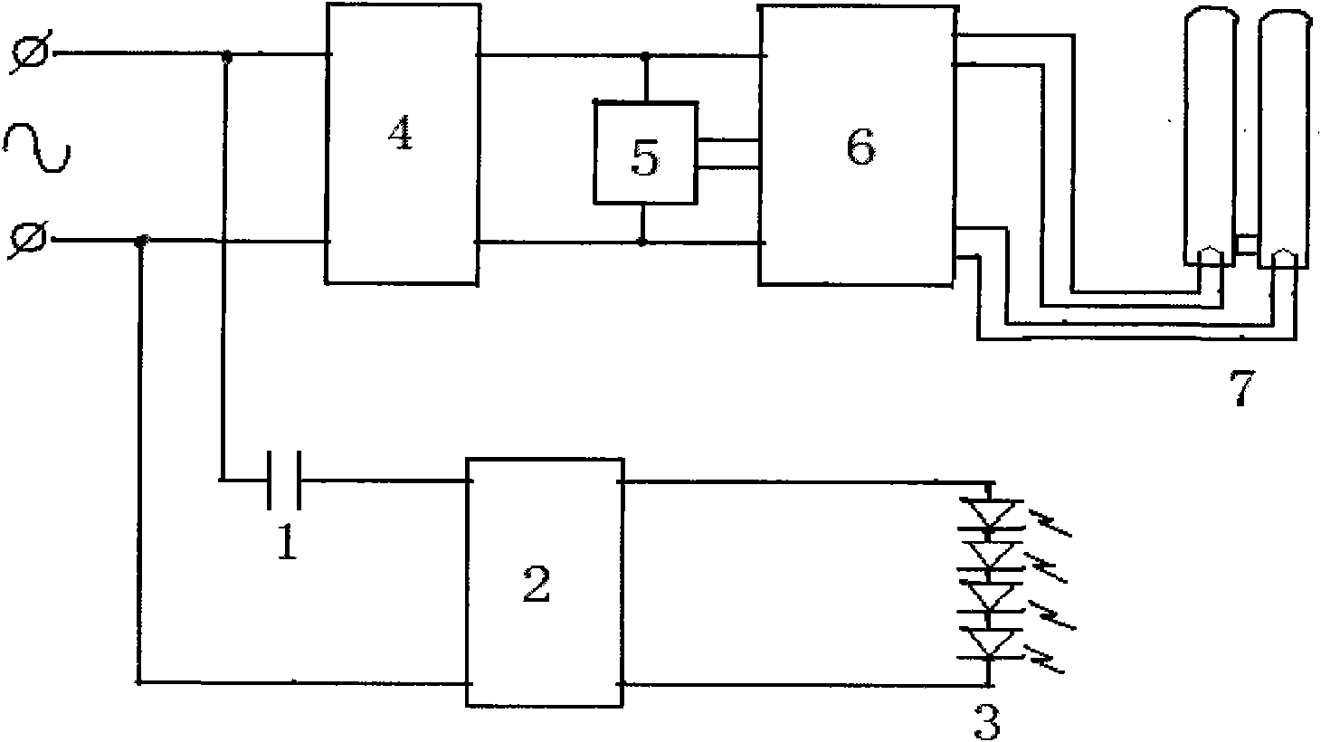
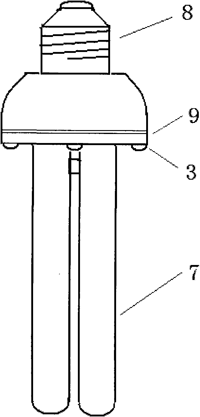
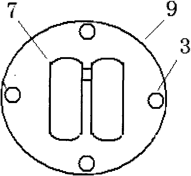
[0018] figure 1 It is a circuit principle block diagram of Embodiment 1 of the present invention, figure 2 , image 3 It is the structural representation of this embodiment 1. This embodiment is a dual-purpose energy-saving lamp suitable for 220V AC power supply voltage. The two light sources used are a 15W 2U-shaped CFL and four low-power LEDs with a rated current of 20mA and power not greater than 0.1W. The electronic ballast circuit of CFL is a conventional circuit, but the conventional trigger circuit is changed to a time-limited trigger circuit, and the time constant of the RC circuit is adjusted so that it can be turned on again after the power is turned off for 3 seconds / 10 seconds. Generate a trigger signal and trigger the electronic ballast circuit to generate high-frequency oscillation to light up the 2U-shaped CFL; when the power is turned off within 1 second / 2 seconds and the power is turned on immediately, the time-limited trigger circuit cannot generate a trig...


PUM


Abstract

The invention discloses a dual-purpose energy-saving lamp, which comprises two light sources including a compact fluorescent lamp (CFL) and low-power LEDs. The dual-purpose energy-saving lamp is characterized in that a general-use switch is used for controlling the dual-purpose energy-saving lamp to have two functions of normal illumination and low-light illumination according to the following mode: when the lamp is turned on after being turned off for a plurality of seconds, the CFL in the lamp is illumined to serve as the normal illumination; and when the lamp is turned on just after being turned off, only the LEDs in the lamp are illumined to serve as the low-light illumination. The control mode is convenient to use and the cost of a circuit is very low; the LEDs in the lamp consist of 2 to 20 low-power LEDs with the power of not more than 0.2 W connected in series so that the costs of the LEDs and a drive circuit thereof are reduced to the lowest; the low-power LEDs are arranged on a plurality of parts of a shell of the lamp so that the irradiating range of the LEDs is increased and the low-light illumination effect is improved; and a user uses the low-power LEDs to replace the CFL when only the low-light illumination is needed, and the electricity saving ratio reaches up to 98 percent. The dual-purpose energy-saving lamp is suitable for use in extensive families and other indoor illuminations.

Description

technical field [0001] The invention relates to a dimming lighting appliance, especially a dual-purpose light source that includes compact fluorescent lamps CFL and LEDs and can be controlled by a common switch to turn on the CFL as normal lighting and turn on the LED as low-light lighting. energy-saving lamps. technical background [0002] At present, lighting electricity consumption accounts for about 12% of the total electricity consumption in my country, and about 18% in developed countries, so saving lighting electricity consumption is of great significance. In the application of indoor lighting, people need normal lighting for work, study, housework and conversation, etc. However, when people are done with these things that require bright lighting, it is enough to maintain low lighting in the place. This kind of low-light lighting saves power, but it can see objects and colors clearly, allowing people to pass by conveniently and do various things such as pouring wate...

Claims


Application Information

Patent Timeline
Patent Type & Authority Applications(China)
IPC IPC(8): H05B35/00H05B37/02H05B41/36F21V23/00F21Y113/02F21Y103/00F21Y101/02F21Y113/20
CPCY02B20/19Y02B20/42Y02B20/40Y02B20/00
Inventor 李先栗李博
Owner 李博
Why Eureka
Try Eureka