Highway Tunnel Lighting Control System

A technology for lighting control systems and road tunnels, applied in the field of lighting control systems, can solve the problems of not being able to observe the tunnel driving environment, hidden safety hazards, driving accidents, etc., to reduce the incidence of traffic accidents, save lighting power consumption, and benefit environmental protection Effect

Active Publication Date: 2017-04-26
CHONGQING JIAOTONG UNIVERSITY
View PDF3 Cites 0 Cited by
  • Summary
  • Abstract
  • Description
  • Claims
  • Application Information

AI Technical Summary

Problems solved by technology

[0002] With the development of the modern highway network, more and more tunnels are becoming more and more, and the control of tunnel lighting has an increasingly important impact on road traffic safety. The lighting lamps in the existing highway tunnels all work by means of general lighting. , that is, all the lighting lamps in the tunnel work in the same working mode, that is to say, the working brightness of all the lighting lamps is the same (due to the differences between individual lighting lamps and lighting control equipment, there are brightness differences, but the brightness difference is small ), but there are serious potential safety hazards in the existing working method: if the ambient light outside the tunnel on the entrance side of the tunnel is greater than the illumination intensity inside the tunnel, then the vehicle just enters the tunnel for a short time or when it is about to enter the tunnel, the tunnel It is equivalent to a "black hole". The driver cannot observe the driving environment in the hole. If the ambient light outside the tunnel on the entrance side of the tunnel is less than the lighting intensity inside the tunnel, then the vehicle will enter the tunnel within a short time or will soon enter the tunnel. At the same time, the driver will have a glare phenomenon, and it is also impossible to observe the driving environment in the tunnel. Of course, the same phenomenon is also true at the exit side of the tunnel. one of the reasons

Method used


Image

  • Highway Tunnel Lighting Control System
  • Highway Tunnel Lighting Control System

Examples


Embodiment Construction

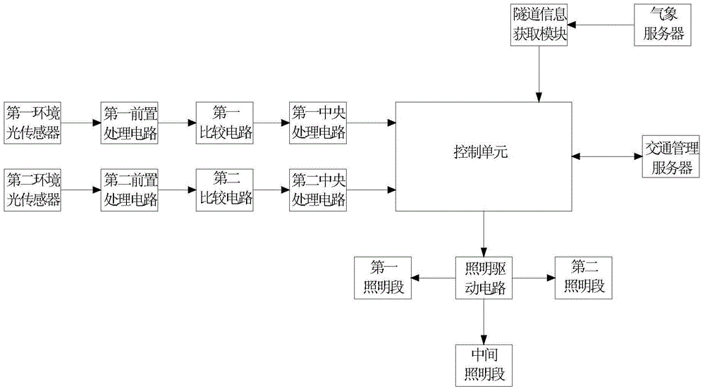
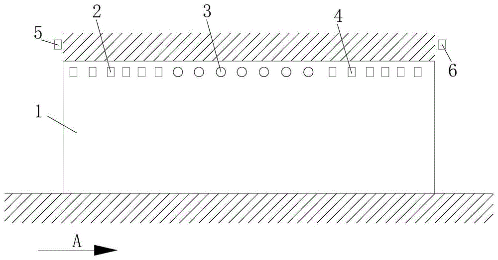
[0014] figure 1 It is a structural principle block diagram of the present invention, figure 2 It is a schematic diagram of the arrangement structure of the tunnel lighting lamp of the present invention, as shown in the figure, wherein figure 2 Among them, A represents the driving direction. A road tunnel lighting control system provided by the present invention includes a lighting unit, a first detection unit, a second detection unit and a lighting control unit; The first ambient light sensor 5 and the first processing unit connected to the output end of the first ambient light sensor, the second detection unit includes a second ambient light sensor 6 arranged at the exit of the tunnel 1 and connected to the second ambient light sensor. A second processing unit connected to the output end of the ambient light sensor, the output ends of the first processing unit and the second processing unit are connected to the control unit, and the control unit outputs a control signal to...


PUM


Abstract

The invention provides an illumination control system for a road tunnel. The illumination control system comprises an illumination unit, a first detection unit, a second detection unit and an illumination control unit, wherein the first detection unit comprises a first environmental light sensor arranged at a tunnel inlet and a first processing unit connected with an output end of the first environmental light sensor; the second detection unit comprises a second environmental light sensor arranged at a tunnel outlet and a second processing unit connected with an output end of the second environmental light sensor; output ends of the first processing unit and the second processing unit are connected with the control unit; the control unit is used for outputting a control signal to the illumination unit; the illumination unit at least comprises an illumination lamp; the illumination lamps are arranged in sequence in a traveling direction of a tunnel and form a first illumination section, a middle illumination section and a second illumination section. Therefore, a black hole or dazzle light phenomenon appearing when a vehicle enters the tunnel or leaves from the tunnel can be effectively eliminated, a driver can be guaranteed to accurately adapt to an illumination environment of the tunnel and accurately observe a traveling environment, and the traffic accident rate of vehicle traveling in the tunnel is greatly reduced.

Description

technical field [0001] The invention relates to a lighting control system, in particular to a highway tunnel lighting control system. Background technique [0002] With the development of the modern highway network, more and more tunnels are becoming more and more, and the control of tunnel lighting has an increasingly important impact on road traffic safety. The lighting lamps in the existing highway tunnels all work by means of general lighting. , that is, all the lighting lamps in the tunnel work in the same working mode, that is to say, the working brightness of all the lighting lamps is the same (due to the differences between individual lighting lamps and lighting control equipment, there are brightness differences, but the brightness difference is small ), but there are serious potential safety hazards in the existing working method: if the ambient light outside the tunnel on the entrance side of the tunnel is greater than the illumination intensity inside the tunnel,...

Claims


Application Information

Patent Timeline
Patent Type & Authority Patents(China)
IPC IPC(8): H05B37/02
Inventor 潘国兵陈蔚
Owner CHONGQING JIAOTONG UNIVERSITY
Why Eureka
Try Eureka