Liquid visualized apparatus and method for dual-polar plate flow field

A fluid supply device, bipolar plate technology, applied in battery electrodes, electrochemical generators, fuel cell additives, etc., can solve problems such as affecting accuracy, inability to use rubber and plastic materials, and high requirements for transparent devices

Active Publication Date: 2008-02-06
SUNRISE POWER CO LTD
View PDF0 Cites 19 Cited by
  • Summary
  • Abstract
  • Description
  • Claims
  • Application Information

AI Technical Summary

Problems solved by technology

The common disadvantage of these methods is that there are high requirements for transparent devices. Because of the application of organic solvents, rubber and plastic materials cannot be used, especially for bipolar plate sealing materials, which have a swelling effect. In addition, the dissolution and mixing of fluorescent dyes are uniform. The accuracy and speed cannot be grasped and characterized, and the fluorescence tracer noise is large, which affects the accuracy of observation

Method used


Image

  • Liquid visualized apparatus and method for dual-polar plate flow field

Examples


Embodiment Construction

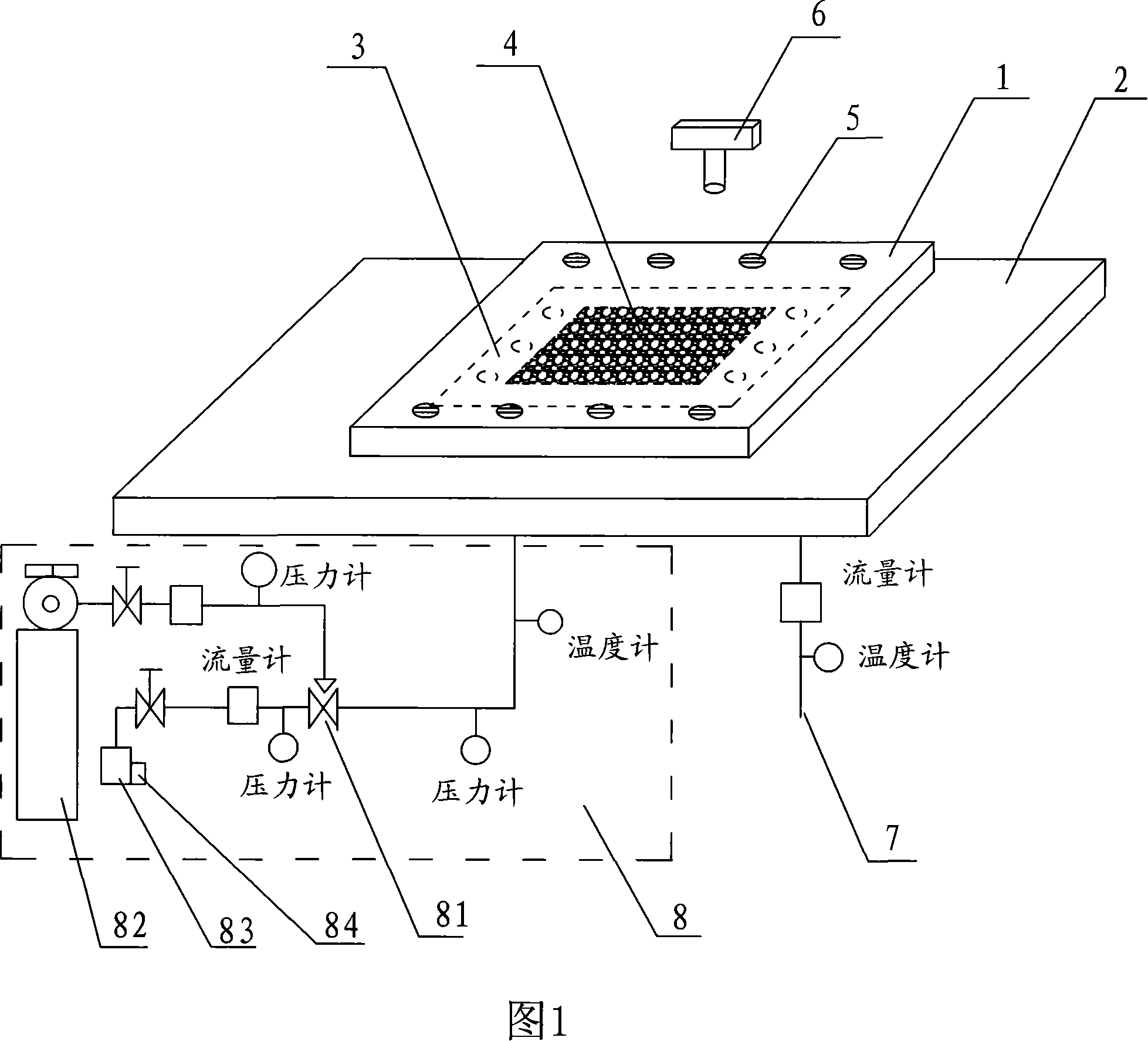
[0015] As shown in Figure 1, the bipolar plate 3 is sandwiched between the transparent cover plate 1, that is, the transparent glass block and the bottom plate 2, and fixed with fastening bolts 5, and the fixing force is controlled with a torque wrench. Here, the gas supply device 82 uses a compressed nitrogen gas storage device Enter the three-way valve 81 through a pressure reducing valve, a needle valve, a flow meter, and a pressure gauge (the air can also be injected into the three-way valve by an air compressor), and enter the inlet of the bipolar plate 3 to reach the flow through the adjustable flow three-way valve 81. Field 4, the water is poured into the pipeline through the pump, and the flowmeter and pressure gauge are connected to the pipeline to measure the flow pressure of the water. The liquid supply device 83 is equipped with a heating device 84, which can adjust the temperature and enter the three-way valve. Form a two-phase flow with nitrogen, and the pipeline ...


PUM


Abstract

The present invention discloses a visualized device of a double pole plates flow field fluid and the technique. The device comprises the double polar plates, a camera, the flow field on the polar plates, a transparent cover plate, a base plate and a supply device of the fluid. Wherein, the positions of the inlet and outlet of the double polar plates on the base plate are provided with the passage of the fluid body. The supply device of the fluid body comprises an air supply device and a liquid supply device. A conducting pipeline is provided with a three-way valve of a mixing unit, the three-way valve mixes the air and the liquid, and also conducts the fluid to the inlet terminal of the double polar plates flow field. When in use, the double polar plates are clamped between the transparent plate and the base plate and further fastened by a fastening bolt. The supply device of the fluid injects fluid into the flow field on the double polar plate and then makes records with the camera. The device solves the problems on fluid choosing and observing methods, the adopted fluid and the methods are simple and practical, and can more accurately and rapidly observe the demanded results, thus can be used in the detection on polar plates and can also be extensively promoted.

Description

technical field [0001] The invention relates to a device for detecting the movement law of fluid in a flow field, in particular to a fluid visualization device and method for a bipolar plate flow field. Background technique [0002] The fuel cell bipolar plate is divided into cathode plate, anode plate, cooling chamber flow field plate. Both the cathode plate and the anode plate have channels that meet the requirements of fuel cell transportation and discharge, also called flow field. The flow field is composed of flow field grooves and flow field ridges. The shape of the flow field can be designed according to the law of fluid motion. field has a significant impact on fuel cell performance. [0003] The visualization of the fluid is in the literature F.Barreras*, A.Lozano, L Vali~no, C.Mar′in, A.Pascau: Flow distribution in a bipolar plate of a proton exchange membrane fuel cell: experiments and numerical simulation studies, Journal Described in detail in of Power Sources...

Claims


Application Information

Patent Timeline
Patent Type & Authority Applications(China)
IPC IPC(8): H01M8/02H01M8/04H01M4/86H01M8/00H01M8/0258
CPCY02E60/50
Inventor 侯中军傅云峰徐乃涛明平文
Owner SUNRISE POWER CO LTD
Why Eureka
Try Eureka