Method and Apparatus of Tilted Illumination Observation

Inactive Publication Date: 2010-02-11
HITACHI HIGH-TECH CORP
View PDF71 Cites 19 Cited by
  • Summary
  • Abstract
  • Description
  • Claims
  • Application Information

AI Technical Summary

Benefits of technology

[0014]Namely, this invention extracts the blurring from the scanning spot during tilted illumination observation by deconvolution from the two images made up of the image taken from right above the reference specimen and the image acquired with the tilted beam, and improve

Problems solved by technology

In the case of (4), a primitive tilted illumination causes the blurring of the beam, so there is a loss of resolution.
However, the technique described above in (1) through (3) need to incline the specimen stage or the SEM column, so the distance between the specimen and the objective lens cannot be narrowed in order to secure the space.
Moreover, resolution improvement technique using a retarding electrical field cannot be utilized, because the specimen and the objective lens are not placed in parallel during tilt observation.
As a result, resolution is inferior in the tilt observation compared with the top down observation.
Further, problems are that it costs to add the hardware of the specimen tilt mechanism, it takes time to the tilt operation; therefore, the observation throughput deteriorates when frequently performing tilted illumination observation.
The technology in (4a) an aberration corrector removes aberrations increasing via the tilt so that high resolution duri

Method used


Image

  • Method and Apparatus of Tilted Illumination Observation
  • Method and Apparatus of Tilted Illumination Observation
  • Method and Apparatus of Tilted Illumination Observation

Examples


first embodiment

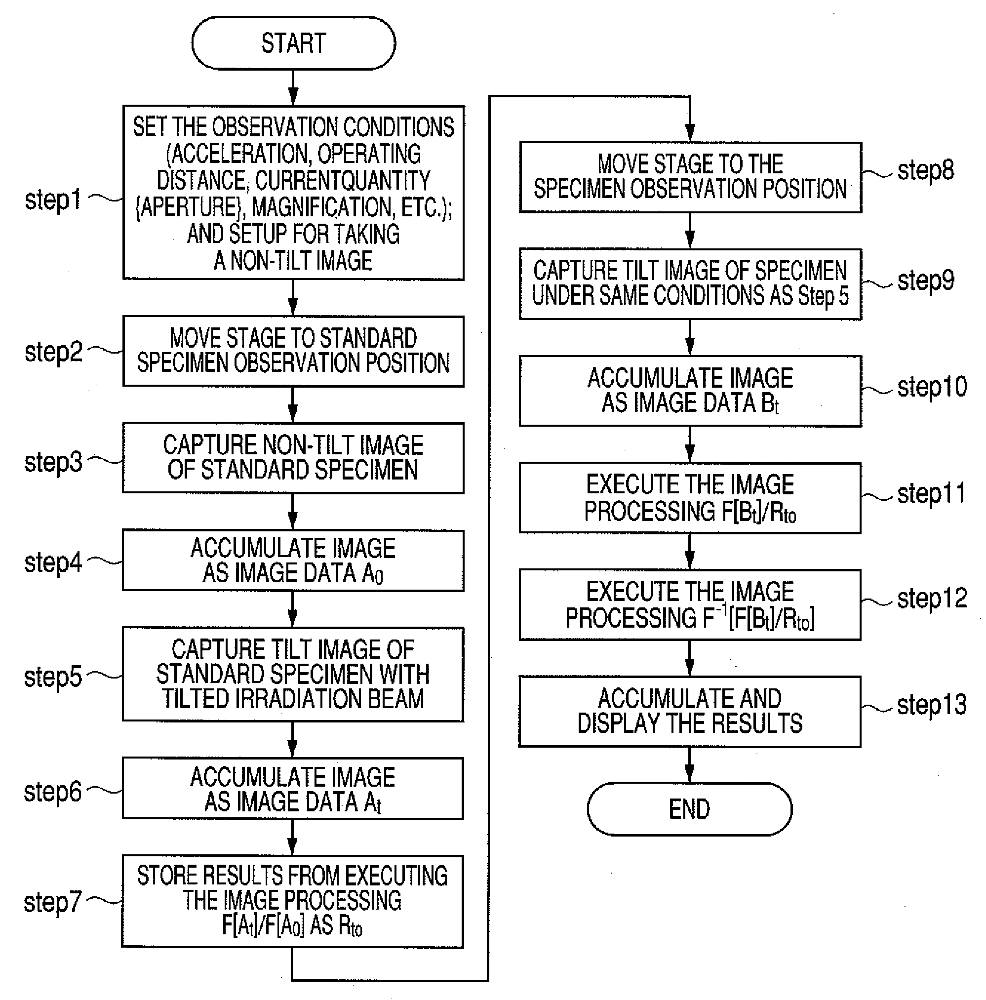
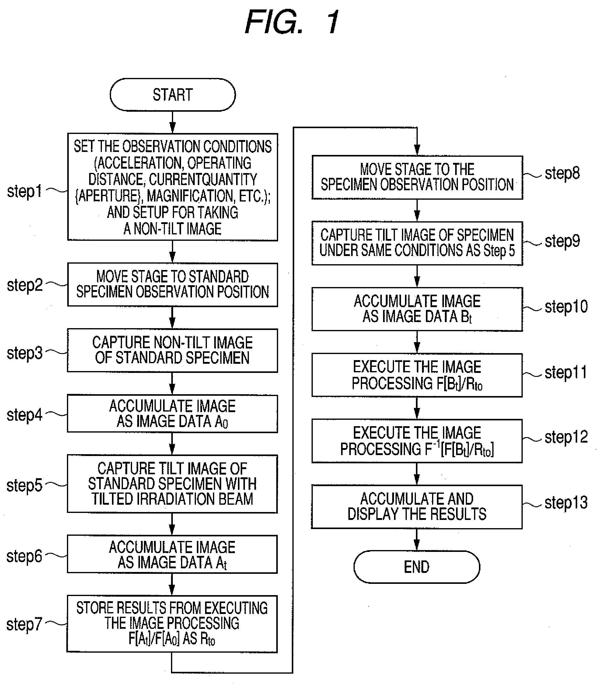
[0037]The procedure in the tilted illumination observation method of the first embodiment for acquiring a tilt high resolution image is described while referring to FIG. 1.

[0038]The operator first of all decides the SEM observation conditions (acceleration voltage, working distance: WD, electrical current quantity, and magnification, etc.) and sets a state for capturing non-tilt images (STEP 1). The specimen stage is next shifted to the standard specimen position built into a section of the specimen stand (STEP 2). An image is then captured at the magnification that the operator wants to observe the non-tilt irradiation image of the standard specimen (STEP 3). This image is accumulated as image data A0 in the memory unit. An optional name may be used as the name of the image from here onwards (STEP 4).

[0039]The beam is then tilted to acquire a tilt image of the standard specimen (STEP 5). If the beam tilt angle and azimuth must be found because three-dimensional processing or other ...

second embodiment

[0047]The structure of the critical dimension SEM serving as the tilted illumination observation apparatus of the first embodiment of this invention is shown next in FIG. 4.

[0048]In FIG. 4, a Schottky emitter 1 is an electron supply utilizing the Schottky effect to disperse for example oxygen and zirconium into single-crystal tungsten. A suppressor electrode 2 and an extraction electrode 3 are installed in the vicinity of the Schottky emitter 1. Heating the Schottky emitter 1 and then applying a voltage of approximately +2 kilovolts across the extraction electrode 3 and Schottky emitter 1 causes it to emit Schottky electrons. A negative voltage applied to the suppressor electron 2 suppresses electrons emitted from other than the tip of the Schottky emitter 1. Electrons leaving from the hole in the extraction electrode 3 are accelerated and converged to the desired acceleration voltage by the static lens formed by the first anode 4 and the second anode 5.

[0049]Electrons that left the...


PUM


Abstract

A tilted illumination observation method and observation device with easy adjustment, high speed, good reproducibility and low cost is provided. A high resolution tilt image of a specimen is obtained by extracting the blurring on the scanning spot occurring during beam tilt from the image (step 6) captured by the tilted beam, and the image (step 4) captured from directly above the standard specimen; and then deconvoluting (step 11, 12) the tilted image of the target specimen (step 10) using the extracted scanning spot from the oblique beam.

Description

CLAIM OF PRIORITY[0001]The present application claims priority from Japanese patent application JP 2008-203196 filed on Aug. 6, 2008, the content of which is hereby incorporated by reference into this application.FIELD OF THE INVENTION[0002]The present invention relates to a charged particle beam apparatus, and relates in particular to tilted illumination observation technology such as for microscopes, inspection apparatuses, length measurement apparatuses and machining apparatuses for scanning a focused charged particle beam on the specimen surface.BACKGROUND OF THE INVENTION[0003]Along with progress made in recent years in reducing the size of semiconductors, a new type semiconductor possessing a three-dimensional structure such as the Fin Field Emission Transistor (FinFET) has started to appear. Along with these new type semiconductors, the critical dimension measurement devices and scanning devices used for semiconductor production and research require the capability to observe ...

Claims


Application Information

Patent Timeline
IPC IPC(8): H04N7/18G01N23/00G01N23/20
CPCG01N2223/302G01N23/203
Inventor KAWASAKI, TAKESHINAKANO, TOMONORIHIROSE, KOTOKO
Owner HITACHI HIGH-TECH CORP
Why Eureka
Try Eureka