Field holographic display system

A holographic display and holographic technology, applied in the field of 3D display, can solve problems such as limited display space, difficulties, and limited viewing angles, and achieve the effects of avoiding visual fatigue, improving visual acuity, and free viewing angles

Pending Publication Date: 2019-11-19
JINGMEN CITY DREAM EXPLORATION TECH CO LTD
View PDF2 Cites 21 Cited by
  • Summary
  • Abstract
  • Description
  • Claims
  • Application Information

AI Technical Summary

Problems solved by technology

[0004] The patent with the application number CN107831558A provides an equivalent negative refractive index plane lens and designs an air projection, but it needs to use a large-area plane display device, and it can only be displayed in front of the screen. The device is very bulky and the display space Limited, the display position is fixed, so that the viewing angle is limited, and it cannot be observed if it is offset by a certain angle, and it is very difficult to achieve a real 3D display, and it can only achieve an effect similar to Pepper's phantom

Method used


Image

  • Field holographic display system
  • Field holographic display system
  • Field holographic display system

Examples


Embodiment 5

[0055] Embodiment 5 is the best embodiment for fixed display applications. In order to further illustrate the influence of the weight W of the holographic projector 1 on the system, on the basis of Embodiment 5, the weight W of the holographic projector 1 is used as a variable:

[0056]

Embodiment 10

[0057] Embodiment 10 and Embodiment 11 further illustrate that in fixed display applications, the influence of the weight W of the holographic projector 1 on the system is limited to the stability.

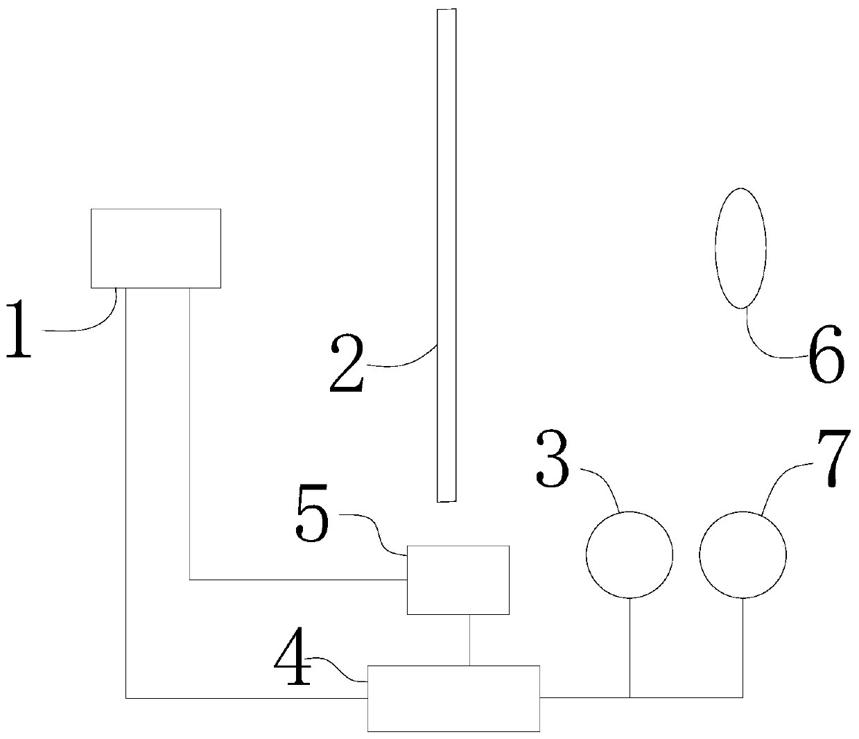
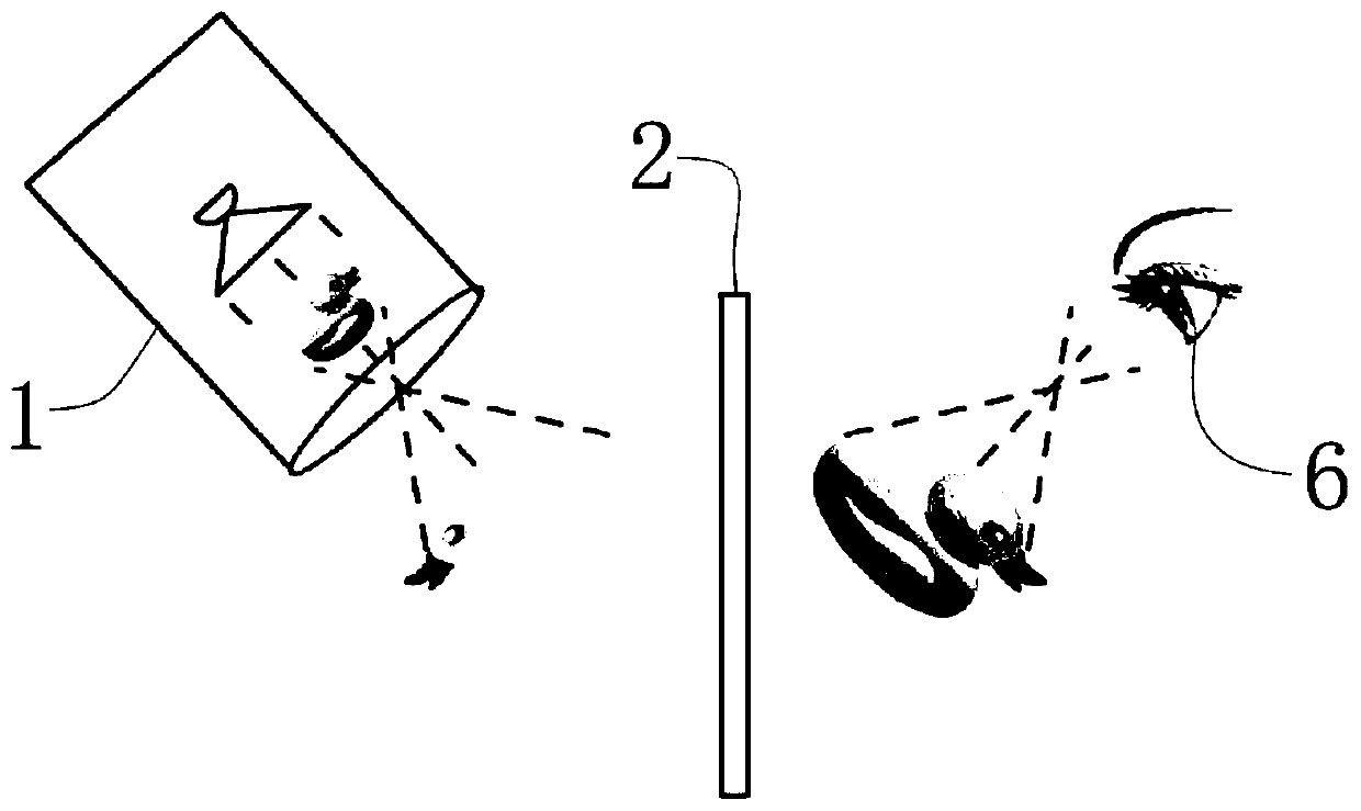
[0058] 2) Wearable display

[0059] For head-mounted display applications, the relative positions of the user's eyes 6 and the system are fixed, so the eye tracking unit 31 can be eliminated.

[0060] In practical application, if the mass W of the holographic projector 1 is large, it will cause inconvenience to wear, and the holographic projector 1 adopts a miniature model, and the mass W is relatively small, and the conventional W is 5g-15g. When using the following examples for illustration, the weight W of the holographic projector 1 is preferably 10 g, the lens diameter (light-transmitting portion) D of the holographic projector 1 is 1 mm to 15 mm, and the maximum length L in the horizontal direction of the projection screen 2 is 0.8 cm to 0.8 cm. 5cm, as shown in the followi...

Embodiment 16

[0063] Embodiment 16 is the best embodiment of wearable display.

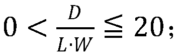
[0064] Based on the data of the above embodiments, the lens diameter (light-transmitting part) D of the holographic projector 1 takes the maximum value of 80 mm for fixed display applications, and the weight (excluding the mass of auxiliary parts such as wire harnesses) W takes the minimum value of 5 g for wearable display applications , the maximum length L of the projection screen 2 in the horizontal direction takes the minimum value of 0.8cm for wearable display applications, and it can be obtained that So in limited range of

[0065] And also show through above-mentioned embodiment, Within the scope of the present invention, the system of the present invention can realize the effect of holographic display, but only when the lens diameter (light-transmitting part) D, weight W of the holographic projector 1 and the maximum horizontal length L of the projection screen 2 are both Only when it is optimal...


PUM


Abstract

The invention belongs to the field of 3D display and discloses a field holographic display system. The system comprises a holographic projector, a projection screen, an interaction response unit and aprocessor; the holographic projector is corresponding to the projection screen in position; the holographic projector and / or the projection screen is provided with a movement executing mechanism connected with the processor; the processor is electrically connected with the holographic projector, the interaction response unit and the movement execution mechanism; the holographic projector projectsa divergent 3D image in the air; additional reference light sources are not needed; after the 3D image is converted through the projection screen of an equivalent negative-refractive index plane lens, a 3D image which can be observed and floats in the air can be obtained, and therefore, cost is reduced; the 3D image can be also displayed in front of or behind the projection screen, and display space is infinite; and an ultra-large picture and an ultra-deep field depth can be displayed in extremely small equipment space.

Description

technical field [0001] The invention relates to the field of 3D display, in particular to an on-site holographic display system. Background technique [0002] 3D display technology can provide depth information, thereby displaying a more realistic display scene. Current mainstream 3D display solutions (such as 3D movies in theaters) are all pseudo 3D display images based on parallax image pairs, and cannot display real 3D images. Although many 3D display technologies have been proposed, none of them can truly display large-scale, stable, high-quality 3D images. Holographic display is considered to be the ultimate solution in the display field, but it is difficult to achieve commercial application in the short term due to its extremely strict requirements on equipment and environment. [0003] The authorized notification number is CN106773469B, which provides a brand-new on-site reproduction holographic solution. In order for the human eye to observe and display large-scale...

Claims


Application Information

Patent Timeline
Patent Type & Authority Applications(China)
IPC IPC(8): G03B35/18G03H1/12H04N13/363H04N13/366H04N13/128H04N13/398H04N9/31G03B30/00
CPCG03B35/18G03H1/12H04N13/363H04N13/366H04N13/128H04N13/398H04N9/3141G03H2001/0088
Inventor 王广军余为伟
Owner JINGMEN CITY DREAM EXPLORATION TECH CO LTD
Why Eureka
Try Eureka