
Transformer substation patrol robot position detecting method based on high-frequency injection method

A technology of high-frequency injection and detection method, applied in the direction of electronic commutator, etc., can solve the problems of reducing system reliability, increasing system hardware cost and maintenance cost, reducing power density, etc., to save hardware cost and maintenance, avoid Multiple saliency effect of motor, effect of improving anti-interference and robustness

Inactive Publication Date: 2014-08-20
SOUTHEAST UNIV
View PDF4 Cites 18 Cited by
  • Summary
  • Abstract
  • Description
  • Claims
  • Application Information

AI Technical Summary

Problems solved by technology

However, the existence of mechanical sensors has brought many disadvantages: 1) The number of connection elements between the motor and the controller increases, the pit interference ability becomes worse, and the system reliability is reduced; 2) The space size and volume of the motor are increased, reducing the Increase the power density, increase the hardware cost and maintenance cost of the system; 3) In high temperature and strong corrosion environment, the performance of the sensor will deteriorate or even fail, resulting in the failure of the motor drive system to work normally
[0003] Whether the initial position of the rotor can be accurately estimated is a prerequisite for the high-performance control strategy (vector control or direct torque) of the permanent magnet synchronous generator and the realization of position sensorless operation. It is also related to whether the robot can start smoothly and whether it can realize The key issue of maximum torque starting; therefore, the detection of the initial rotor position has always been one of the hot and difficult issues in the engineering and technology circles, especially in electric robots, because the operation of the robot is basically a high-voltage operation, and the detection line is very Danger, if the initial position detection of the rotor is inaccurate, it will cause the electric robot to reverberate and rotate, and as a result, the entire power line and the robot may be damaged due to misoperation, and even cause a high-voltage short circuit in severe cases

Method used


Image

  • Transformer substation patrol robot position detecting method based on high-frequency injection method
  • Transformer substation patrol robot position detecting method based on high-frequency injection method
  • Transformer substation patrol robot position detecting method based on high-frequency injection method

Examples


Embodiment Construction

[0017] The present invention will be further described below in conjunction with the accompanying drawings.

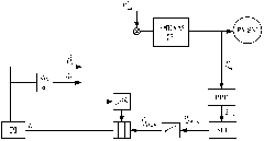
[0018] A position detection method for substation inspection robots based on high-frequency injection method, which combines initial position tracking closed-loop control system, rotating high-frequency voltage injection method, PMSM inductance identification model, multi-saliency decoupling observer and rotor position anti-interference observer Carry out rotor position angle detection together, specifically include the following steps:

[0019] (1) When detecting the initial position of the PMSM rotor, the initial position tracking closed-loop control system is adopted. Inject a high-frequency voltage signal into the coordinate system, and estimate the initial position of the PMSM rotor by constructing a rotor position tracking closed-loop system;

[0020] (2) After the substation inspection robot is running, the rotating high-frequency voltage injection method is u...


PUM


Abstract

The invention discloses a transformer substation patrol robot position detecting method based on a high frequency injection method. According to the method, an initial position tracking closed-loop control system, a rotating high frequency voltage injection method, a PMSM inductance identification model, a multiple-salient-pole decoupling observer and a rotor position anti-interference observer are combined together to conduct rotor position angle detection. By means of the transformer substation patrol robot position detecting method based on the high frequency injection method, the smooth starting of the transformer substation patrol robot PMSM is achieved, and precise, effective and real-time detection of the rotor position information of the transformer substation patrol robot PMSM can be achieved.

Description

technical field [0001] The invention relates to a position detection method of a substation inspection robot based on a high-frequency injection method, which includes an initial position tracking closed-loop control system, a rotating high-frequency voltage injection method, a PMSM inductance identification model, a multi-salient pole decoupling observer, and rotor position anti-interference The observers are combined to detect the rotor position angle. Background technique [0002] At present, in robot systems of various structures, the scheme of using permanent magnet synchronous motor (PMSM) has a high efficiency, so this scheme plays an important role. Especially in electric robots and small robots, PMSMs have been more used due to these advantages. However, in general, the driving motor of the robot uses a mechanical position sensor to detect the speed of the motor and the position of the mover, such as a photoelectric encoder and a resolver. However, the existence o...

Claims


Application Information

Patent Timeline
Patent Type & Authority Applications(China)
IPC IPC(8): H02P6/16
Inventor 余海涛孟高军胡敏强黄磊
Owner SOUTHEAST UNIV
Learn More