Processing apparatus

A technology of processing equipment and processing department, applied in clothing, underwear, baby underwear, etc., to achieve the effect of restraining tension fluctuations

Inactive Publication Date: 2010-08-18
UNI CHARM CORP
View PDF7 Cites 3 Cited by
  • Summary
  • Abstract
  • Description
  • Claims
  • Application Information

AI Technical Summary

Problems solved by technology

However, this stop affects the transport of processing locations immediately upstream and immediately downstream of the press processing location

Method used


Image

  • Processing apparatus
  • Processing apparatus
  • Processing apparatus

Examples


no. 1 approach

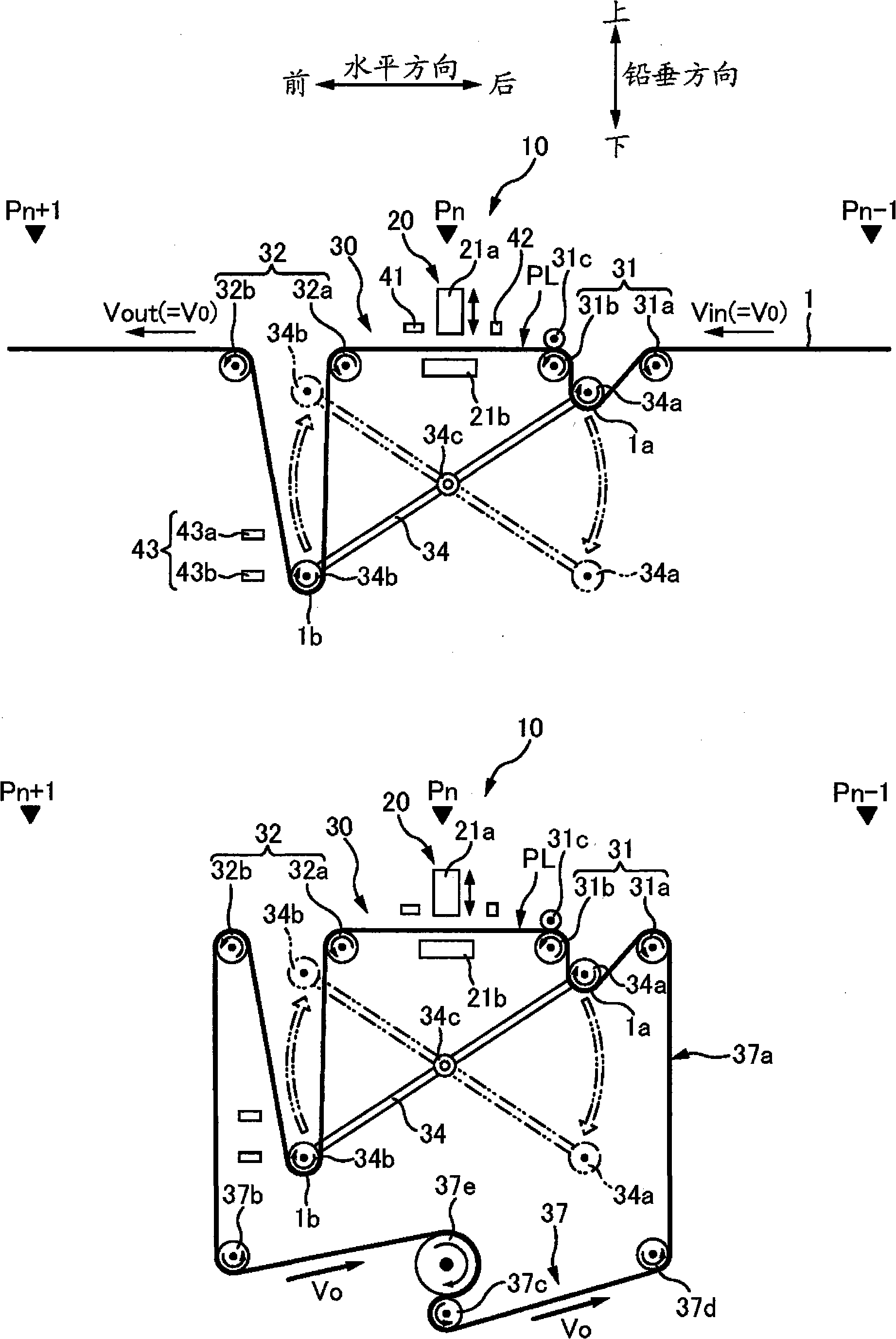
[0117] 4A and 4B are side views of the processing apparatus 10 according to the first embodiment. Note that, for simplicity of the drawing, FIG. 4A shows the processing apparatus 10 without the tension fluctuation suppressing mechanism 37 as a component of the processing apparatus 10, and conversely, FIG. 4B shows the tension fluctuation suppressing mechanism 37 with but without There is a processing device for a strip-shaped workpiece 1 .

[0118] In addition, as shown in FIG. 4A , the vertical direction is hereinafter also referred to as an up-down direction, and the horizontal direction orthogonal to the vertical direction is hereinafter also referred to as a front-rear direction. Incidentally, “front” in the front-rear direction is the downstream side in the conveyance direction of the belt-shaped workpiece 1 , and “rear” is the upstream side in the conveyance direction of the belt-shaped workpiece 1 . In addition, the upstream side of the processing facility 10 is also r...

no. 2 approach

[0163] Fig. 10 is a side view of a processing apparatus 10a according to the second embodiment. In the first embodiment described above, the driving roller 31 b controls the conveyance state of the belt-shaped workpiece 1 in the pressing device 20 . In the present second embodiment, the conveyance state is controlled by a non-driving roller 31d provided with a brake instead of the driving roller 31b and a swing drive device 36 for driving the swing member 34 to swing. In other words, the brake-equipped non-driving roller 31d and the rocking drive device 36 correspond to the "intermittent delivery section". Features other than the above-mentioned features are the same as those in the first embodiment, for example, the tension fluctuation suppressing mechanism 37 is similarly provided.

[0164] The actuator-equipped non-driving roller 31d includes: a non-driving roller 31d installed at the same position as the driving roller 31b instead of the driving roller 31b; and a brake me...


PUM


Abstract

A processing apparatus (10) applies a processing (Pn) to a continuous band-shaped work (1) by intermittently stopping the work (1) which is running along a predetermined running path (PL). In the processing apparatus, a variation in the tension of the work (1) which may be produced by the intermittent stoppage of the work (1) is effectively suppressed. A work conveying part (30) comprises an endless annular body (37a) wrapped around conveying rolls (31, 32), a first mobile body (34a), and a second mobile body (34b). A first drive roll (37e) circulatingly drives the endless annular body (37a) continuously at a predetermined speed so that the endless annular body (37a) performs the same running operation and accumulating operation as the work (1) in the area where the endless annular body (37a) is arranged along the running path. An intermittent feeding part (31b) intermittently stops the endless annular body (37a) when the work (1) is stopped.

Description

technical field [0001] The present invention relates to a processing apparatus for intermittently stopping and processing a continuous strip-shaped workpiece while the workpiece is being advanced along a predetermined travel path. Background technique [0002] As shown in FIG. 1, a conventional production line 5 for, for example, disposable diapers includes a plurality of processing positions P1, P2, . . . arranged one behind the other in the horizontal direction. Semi-finished diapers are continuously conveyed in the form of a continuous strip-shaped workpiece 1, during which various processes are performed on the semi-finished diapers at each processing position P1, P2, . . . , thereby completing the finished product. [0003] In the case of press working at one of the above-mentioned working positions P1, P2, . However, this stop affects the transport of the processing locations immediately upstream and immediately downstream of the press working location. That is, the ...

Claims


Application Information

Patent Timeline
Patent Type & Authority Applications(China)
IPC IPC(8): B65H23/192A61F13/15A61F13/49B65H20/04B65H20/24
CPCB65H2301/4493B65H2403/20B65H20/24A61F13/15764A61F13/15804B65H2408/2174B65H2408/2171B65H2301/4491
Inventor 龟田范朋
Owner UNI CHARM CORP
Why Eureka
Try Eureka