Coating film transfer tool

a technology of transfer tape and film, applied in the direction of erasing devices, thin material processing, printing, etc., to achieve the effect of suppressing the tension change of a piece of transfer tap

Active Publication Date: 2022-11-08
FUJI COPIAN
View PDF20 Cites 0 Cited by
  • Summary
  • Abstract
  • Description
  • Claims
  • Application Information

AI Technical Summary

Benefits of technology

[0021]As described above, with a coating film transfer tool according to the present invention, it is possible to suppress a change in the tension of a piece of transfer tape from the initial phase of usage to the final phase of usage of the coating film transfer tool, without employing a complex structure. Also, there is a very low possibility that looseness of a piece of transfer tape will cause a running failure of the piece of transfer tape.

Problems solved by technology

Therefore, a weak user may be unable to press the transfer head against the transfer target with a sufficient force, unable to draw out a piece of transfer tape T at the transfer head, and accordingly be unable to transfer a coating film.
Also, even if a weak user can transfer a coating film, a transfer failure may occur.
Although it is possible to prevent such a transfer failure from occurring in the final phase of usage by reducing tension that is applied to the piece of transfer tape T in the final phase of use, such reduction causes the problem in which the tension applied to the piece of transfer tape T is too low in the initial phase of usage.
If the tension applied to the piece of transfer tape T is too low in the initial phase of usage, a problem arises in which the piece of transfer tape becomes loose in the initial phase of usage.
If the piece of transfer tape becomes loose near the transfer head, a problem arises in which the coating film cannot be easily cut upon the completion of transfer, for example.
However, if the outer diameter of the feeding core is increased, a problem arises in which the size of the coating film transfer tool will be large.

Method used


Image

  • Coating film transfer tool
  • Coating film transfer tool
  • Coating film transfer tool

Examples


examples

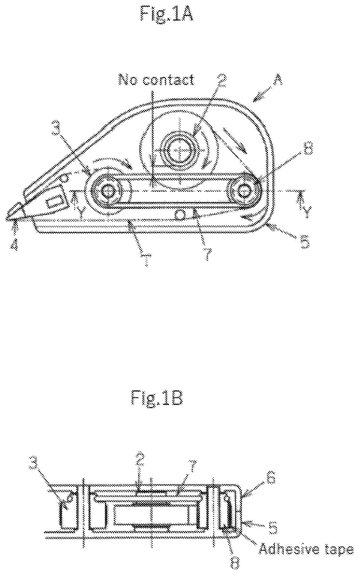
[0054]The coating film transfer tool A according to the first embodiment of the present invention shown in FIG. 1 was prepared as Example 1 of the present invention. In the coating film transfer tool A, the outer circumferential surface of the intermediate roller 8 was made adhesive by attaching an adhesive sheet A11 to the outer circumferential surface of the intermediate roller 8. The adhesive sheet A11 is an adhesive sheet formed by providing a silicone adhesive layer that is mainly composed of addition-curing silicone and has a thickness of 20 μm on one surface of a PET sheet that has a thickness of 50 rpm, and providing a layer of an acrylic adhesive that has a thickness of 20 μm on the other surface of the PET sheet. In the coating film transfer tool A, the acrylic adhesive on the adhesive sheet A11 is attached to the outer circumferential surface of the intermediate roller 8, and therefore the silicone adhesive layer of the adhesive sheet A11 forms the outer circumferential s...


PUM

PropertyMeasurementUnit
tensionaaaaaaaaaa
lengthaaaaaaaaaa
widthaaaaaaaaaa

Abstract

The coating film transfer tool includes: a feeding core around which transfer tape is wound and that feeds a piece of transfer tape, the piece of transfer tape including a piece of base tape and a coating film that is provided on one surface of the piece of base tape; a transfer head that presses the coating film against a transfer target and transfers the coating film thereonto; a winding core that winds up the piece of base tape from which the coating film has been transferred; and an intermediate roller that rotates as the piece of transfer tape travels, in contact with a first surface of the piece of transfer tape fed from the feeding core, the first surface being a surface on which the coating film is not provided. A second surface of the intermediate roller is adhesive with respect to the first surface.

Description

TECHNICAL FIELD[0001]The present invention relates to a coating film transfer tool for press-transferring a coating film for typo correction, an adhesive film for adhesion, a coating film for decoration, or the like to a transfer target.BACKGROUND ART[0002]FIG. 3 is a schematic diagram illustrating a configuration of a conventional coating film transfer tool 1. The coating film transfer tool 1 includes a case 5 and a cover (not shown) that covers an opening in the case 5. The case 5 includes spindles 12 and 14 provided inside thereof, and a feeding core 2 and a winding core 3 are held by the spindles 12 and 14 so as to be rotatable. Also, a transfer head 4 protrudes from the case 5 to the outside. The coating film transfer tool 1 is also provided with transfer tape T that includes base tape with a coating film applied on the surface thereof. Transfer tape T is wound around the feeding core 2. A piece of transfer tape T drawn out from the feeding core 2 is separated into a coating fi...

Claims


Application Information

Patent Timeline
Patent Type & Authority Patents(United States)
IPC IPC(8): B65H18/10B43L19/00B43M11/06B65H23/06B65H35/00
CPCB65H18/10B43L19/00B43M11/06B65H23/06B65H35/0033B65H2301/412B65H2402/41B65H2701/377B65H37/007B65H18/145B65H2403/25
Inventor WATANABE, KAZUYA
Owner FUJI COPIAN
Why Eureka
Try Eureka