Conveyance apparatus of web print medium

a technology of conveying apparatus and web print medium, which is applied in the direction of printing, other printing apparatus, thin material processing, etc., can solve the problems of complicated apparatus configuration, deviating landing position of ink, and reducing print quality, so as to simplify the brake control and suppress the oscillation of web w

Active Publication Date: 2019-01-29
RISO KAGAKU CORP
View PDF12 Cites 0 Cited by
  • Summary
  • Abstract
  • Description
  • Claims
  • Application Information

AI Technical Summary

Benefits of technology

[0009]An object of the disclosure is to provide a conveyance apparatus which can suppress tension change of a web without a tension detector.
[0011]In the aforementioned configuration, it is possible to control the conveyance motor such that conveyance speed of the web is maintained at fixed speed and, at the same time, control the braking force of the brake such that the tension of the web is fixed, without directly detecting the tension of the web. Accordingly, tension change of the web can be suppressed without a tension detector for detecting the tension of the web.
[0013]In the aforementioned configuration, it is possible to finely adjust the braking force of the brake while providing required braking force.
[0015]In the aforementioned configuration, it is possible to omit the adjustment of the braking force while providing braking force required to suppress the oscillation of the web. As a result, it is possible to simplify the brake control while suppressing the oscillation of the web W.

Problems solved by technology

When the distance between the inkjet head and the web changes, there is a risk that the ink landing positions deviate and the print quality decreases.
Meanwhile, providing the tension detector leads to complicated apparatus configuration.
Moreover, the tension detector sometimes causes conveyance failure such as meandering of the web.

Method used


Image

  • Conveyance apparatus of web print medium
  • Conveyance apparatus of web print medium
  • Conveyance apparatus of web print medium

Examples


Embodiment Construction

[0022]In the following detailed description, for purposes of explanation, numerous specific details are set forth in order to provide a thorough understanding of the disclosed embodiments. It will be apparent, however, that one or more embodiments may be practiced without these specific details. In other instances, well-known structures and devices are schematically shown in order to simplify the drawing.

[0023]Description will be hereinbelow provided for embodiments of the present invention by referring to the drawings. It should be noted that the same or similar parts and components throughout the drawings will be denoted by the same or similar reference signs, and that descriptions for such parts and components will be omitted or simplified. In addition, it should be noted that the drawings are schematic and therefore different from the actual ones.

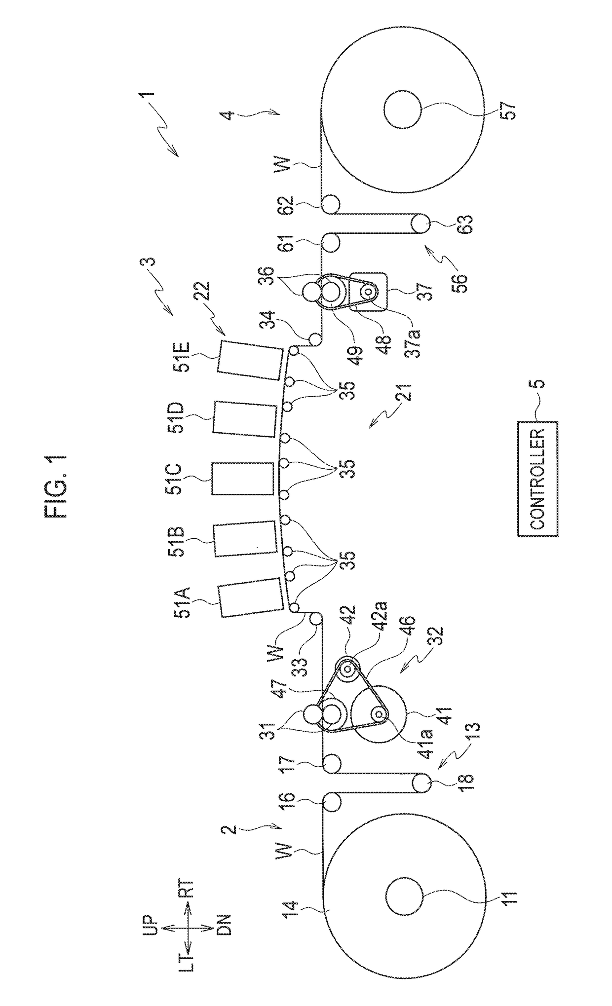
[0024]FIG. 1 is a schematic configuration diagram of a printing apparatus 1 including a conveyance apparatus according to an embodimen...


PUM


Abstract

A conveyance apparatus includes a conveyance roller, a conveyance motor, a back tension roller, a conveyance speed detector, a brake, and a controller. The controller is configured to: based on a conveyance speed of a web detected by the conveyance speed detector, control a value of a drive control parameter of the conveyance motor such that the conveyance speed of the web is equal to a target speed; and, based on an output torque of the conveyance motor corresponding to the value of the drive control parameter, adjust a braking force of the brake applied to the back tension roller which applies a tension to the web such that the tension of the web is equal to a target tension.

Description

CROSS REFERENCE TO RELATED APPLICATION[0001]This application is based upon and claims the benefit of priority from the prior Japanese Patent Application No. 2016-067650, filed on Mar. 30, 2016, the entire contents of which are incorporated herein by reference.BACKGROUND1. Technical Field[0002]The disclosure relates to a conveyance apparatus which conveys a web.2. Related Art[0003]Japanese Unexamined Patent Application Publication No. 2013-71323 proposes a printing apparatus which continuously conveys a long web as a print medium and, at the same time, performs printing on the web by ejecting ink from an inkjet head.[0004]Among printing apparatuses of the aforementioned type, there is one which includes a conveyance roller arranged downstream of the inkjet head and a back tension roller arranged upstream of the inkjet head. The conveyance roller is driven by a motor and conveys the web. A brake is connected to the back tension roller and the back tension roller applies tension to the...

Claims


Application Information

Patent Timeline
Patent Type & Authority Patents(United States)
IPC IPC(8): B41J15/00B41J15/16B65H23/18B41J13/00
CPCB41J13/0009B65H23/1806B41J15/16
Inventor AOKI, KAZUYUKI
Owner RISO KAGAKU CORP
Why Eureka
Try Eureka