Method and device for controlling febric output for loom

A loom and fabric technology, applied in the field of controlling fabric output, can solve the problems of unclear fabric structure boundaries, etc., and achieve the effect of suppressing changes in warp tension and suppressing changes in warp tension

Inactive Publication Date: 2003-07-09
TSUDAKOMA KOGYO KK
View PDF1 Cites 0 Cited by
  • Summary
  • Abstract
  • Description
  • Claims
  • Application Information

AI Technical Summary

Problems solved by technology

[0007] When using the conventional technology, the integral element of the correction calculation device must be unconditionally connected with the final integral value of the previous selection period for each knitting condition. When the knitting condition is switched and changed during the knitting process , the position of the weaving junction (the intersection of the part that has been woven into a woven cloth and the part that exists independently in a thread) will move for a long distance, so it is necessary for the weaving junction to move to the normal state position of various weaving conditions The time will be too long, resulting in the problem that the boundary of the fabric structure is not clear

Method used


Image

  • Method and device for controlling febric output for loom
  • Method and device for controlling febric output for loom
  • Method and device for controlling febric output for loom

Examples


Embodiment Construction

[0032] Hereinafter, embodiments of the present invention will be described with reference to the drawings.

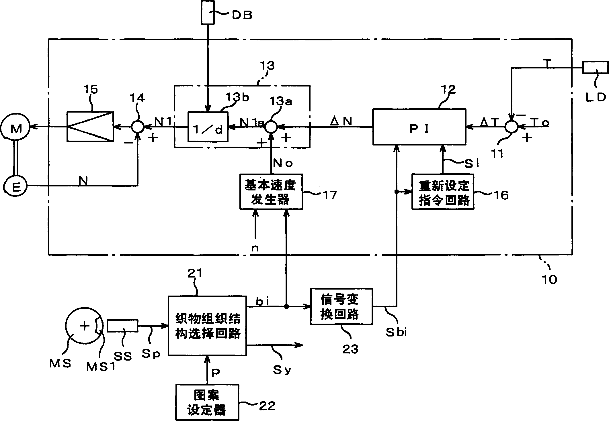
[0033] The output control device 10 of the loom includes a correction calculation device 12, a command speed calculation device 13, and a basic speed generator 17 ( figure 1 ). At the same time, the correction calculation device 12, the command speed calculation device 13, combined with the synthesis points 11, 14, and the control amplifier 15 form a speed control system for the output motor M. exist figure 1 Among them, the output motor M, the tension sensor LD, the roll diameter sensor DB, and the rotation sensor E correspond to Figure 10 Machines with the same symbol in . In addition, a resetting command circuit 16 is attached to the correction calculation device 12 .

[0034] The set tension To set by a setting device not shown and the warp tension To from the tension sensor LD are respectively input to the addition end point and the subtraction end point of the...


PUM


Abstract

The invention is the method and device for controlling febric output for loom. The aim of which is to provide a method of the feed control for a loom capable of clearly expressing a border of textile weave on the woven cloth. This system includes an integration element-containing corrective arithmetic means 12 and a command speed arithmetic means 13; wherein the means 12 functions to selectively couple the integral value of the integration element with either the final integral value in the preceding selective period or a preset value each time weaving conditions P change, thus quickly moving the position of a cloth fell.

Description

technical field [0001] The invention relates to a method and a device for controlling fabric output of a loom, which can clearly show the boundaries of fabric structures with different weaving conditions on the fabric. Background technique [0002] Conventional loom output devices such as Figure 10 As shown, the warp tension T is detected, compared with the set tension To, and the speed of the output motor M is controlled according to the tension deviation ΔT=To-T (JP-A-8-246299). [0003] Warp Y, after being pulled out (reelability) from warp beam B1 (warp beam), passes through heald frame SF (heddle) between tension roller TR1 (tension roller) and take-up roller (take-up roller) After being shed, unillustrated weft threads are woven into, and a woven cloth CL is woven by a loom R (reed), and wound up on a reel B2. In addition, a tension sensor LD (for example, a load cell) capable of detecting warp tension T is attached to the tension roller...

Claims


Application Information

Patent Timeline
Patent Type & Authority Applications(China)
IPC IPC(8): D03D49/10D03D49/04D03D51/00
Inventor 山田茂生山崎守一松山丰
Owner TSUDAKOMA KOGYO KK
Why Eureka
Try Eureka