

Vacuum pump with two helical rotors
A vacuum pump and spiral technology, applied in the field of pumping devices, can solve problems such as unusable, achieve fast rotation, good compression rate, and avoid backflow pollution
Inactive Publication Date: 2010-08-18
ALCATEL LUCENT SAS
View PDF1 Cites 2 Cited by
- Summary
- Abstract
- Description
- Claims
- Application Information
AI Technical Summary
Problems solved by technology
However, this type of pump cannot be used where heating of the gas within the pumping unit is required and / or higher pressures
Factories are always looking to reduce the size and cost of equipment in their manufacturing rooms, especially in the semiconductor industry where clean room space is at a premium
Method used
View moreImage
Smart ImageViewing Examples

Examples
Embodiment Construction
Login to View More PUM
 Abstract
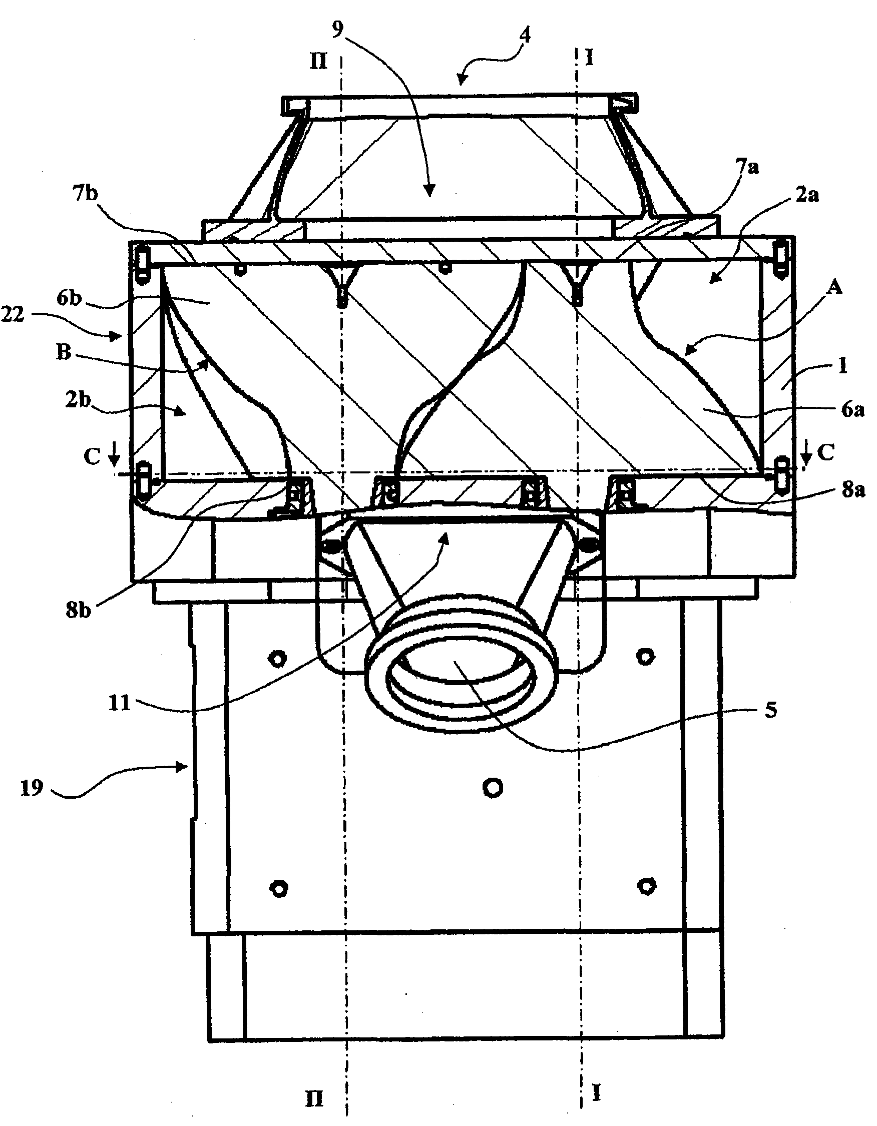
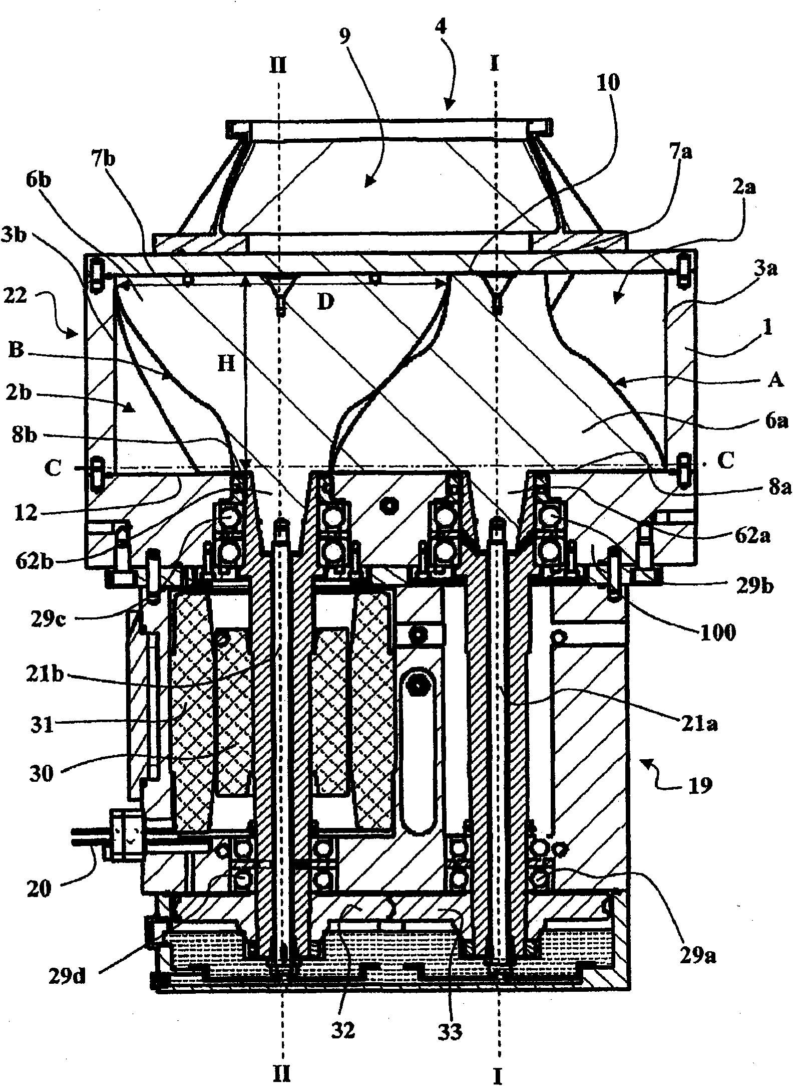
The invention relates to a vacuum pump comprising a housing (1), a mechanical portion (19) and a pumping portion (22). The pumping portion (22) includes two meshed helical rotors (A, B) each having a helical torsion about a longitudinal axis. The rotors (A, B) are short and held in an offset position in the downstream direction. An inlet passage (4) communicates with the inside of the housing (1) via an inlet opening (9). An outlet passage (5) communicates with the inside of the housing (1) via an outlet opening (11). The inlet and the outlet are axial relative to the axes of the helical rotors (I-I, II-II).
Description
technical field The present invention relates to pumping means capable of creating and maintaining a suitable vacuum within an apparatus. Background technique Generating and maintaining a vacuum within equipment is common in industrial semiconductor manufacturing because some manufacturing steps must be performed in a vacuum. During these manufacturing steps, the device is connected to a pumping device that reduces the internal pressure of the device until a suitable vacuum is achieved. In practice, known pumping devices generally include at least one main pump and at least one auxiliary pump, at least one main pump is placed at the discharge port of the vacuum line, and at least one auxiliary pump is connected in series between the main pump and the pump of the equipment in the flow path of the pumped gas. The first known pumping device is used to reduce the pressure in the equipment from about 10 -2 The situation in the pressure interval from mbar to about 10 mbar. ...
Claims
Login to View More Application Information
Patent Timeline
 Patent Type & AuthorityApplications(China)
IPC IPC(8): F04C18/12F04C23/00F04C25/02
CPCF04C2240/402F04C25/02F04C18/126
Inventor伯努特·巴赫德
OwnerALCATEL LUCENT SAS