Lip type seal

A technology of lip seal and sealing parts, applied in the direction of engine seal, variable capacity pump parts, pump components, etc., can solve the problems of reduced sealing performance and blistering of the sealing lip 75, and achieve the effect of improving the blistering resistance

Inactive Publication Date: 2010-08-18
EAGLE INDS
View PDF10 Cites 5 Cited by
  • Summary
  • Abstract
  • Description
  • Claims
  • Application Information

AI Technical Summary

Problems solved by technology

In the above-mentioned bonded lip seal under such use conditions, since the rubber-like elastic sealing lip 75 and the metal reinforcing ring 77 are bonded, when used under high-load conditions, the sealing lip 75 will be damaged. Blistering phenomenon, which becomes the cause of reduced sealing performance

Method used


Image

  • Lip type seal
  • Lip type seal
  • Lip type seal

Examples


no. 1 example

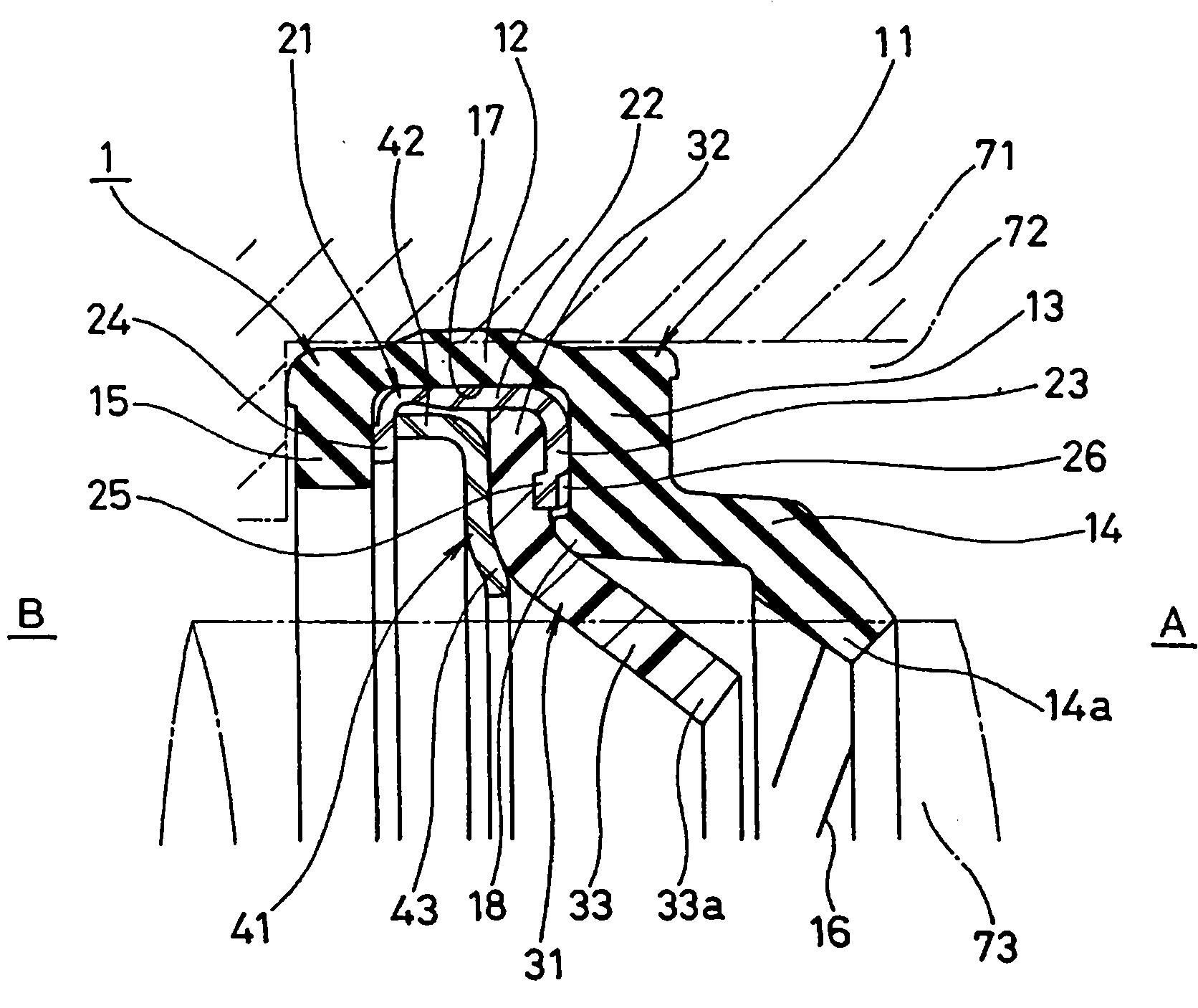
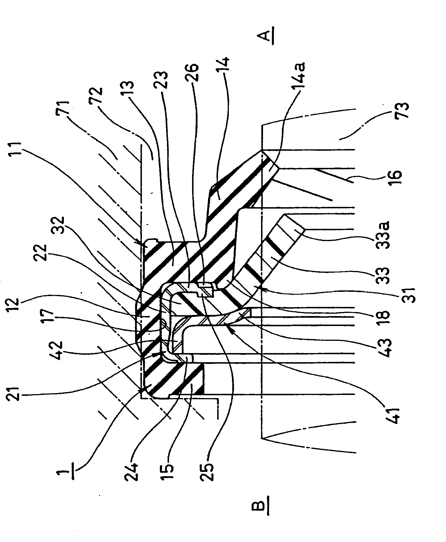
[0078] FIG. 1 shows a cross section of a main part of a lip seal 1 related to a first embodiment of the present invention, and the lip seal 1 is constituted as follows. In addition, this lip seal 1 is used as a water pump seal for automobiles to seal cooling water. The right side of the figure is the cooling water, that is, the seal fluid side A, and the left side of the figure is the atmospheric side B.

[0079] That is, the lip seal 1 is mounted on the inner periphery of the shaft hole (hole) 72 of the casing (pump casing) 71, and is slidably in close contact with the peripheral surface of the shaft (rotation shaft) 73, and is configured to have A double-layered lip structure of the rubber-like elastic sealing lip 14 on the fluid side A and the resin sealing lip 33 arranged on the atmospheric side B.

[0080] In addition, as the components of the lip seal 1, there are the following four parts: the first lip seal member 11 made of a rubber-like elastic body fitted in the inn...

no. 2 example

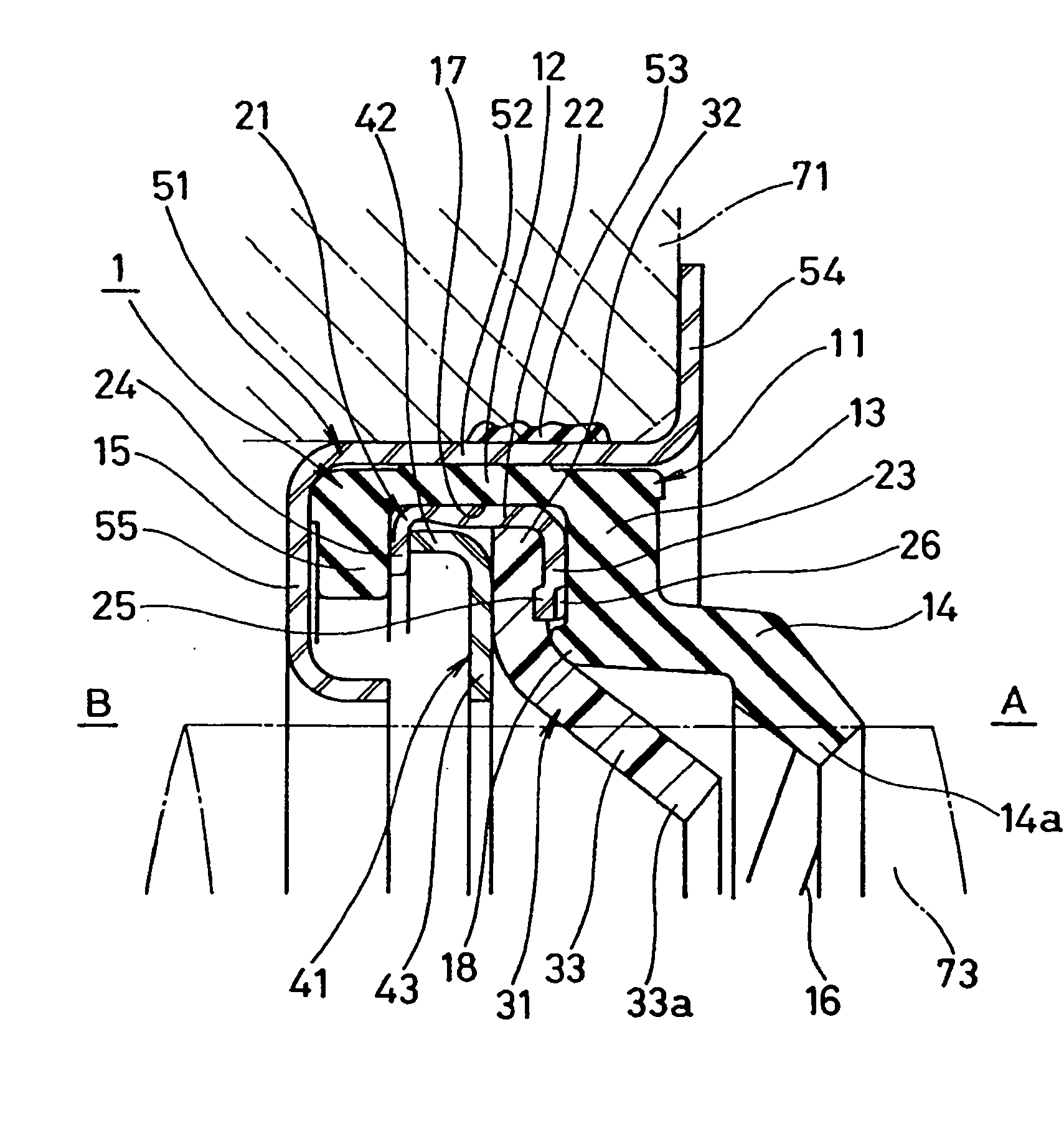
[0097] In addition, in the above-mentioned first embodiment, although the lip seal 1 is directly fitted into the inner periphery of the shaft hole 72 of the casing 71 through the cylindrical portion 12 of the first lip seal member 11, as shown in FIG. It can be installed on the inner periphery of the shaft hole 72 of the casing 71 through the sleeve (metal ring) 51 .

[0098] The sleeve 51 shown in FIG. 2 is made of a predetermined steel material such as metal, such as a stamped product of a metal plate, and is integrally formed into a ring shape. The lip seal 1 having the above-mentioned structure is fitted into the inner peripheral surface of the cylindrical portion 52, and at the same time The outer peripheral surface of the cylindrical portion 52 is fitted into the inner peripheral surface of the shaft hole 72 of the casing 71 . The outer peripheral surface of the cylindrical portion 52 is covered with an outer peripheral seal 53 interposed between the sleeve 51 and the in...

no. 3 example

[0100] In addition, the sleeve 51 may be provided with a stepped shape in a planar shape at right angles to the axis on the cylindrical portion 52, or may be provided with a stepped shape with an S-shaped cross section on the cylindrical portion 52. In the above case, the size (diameter) of the sleeve 51 depends on The radial width of the stepped shape is formed in various ways. Therefore, when the lip seal 1 is installed on the actual machine, by selecting the sleeve 51 consistent with the shaft hole diameter of the actual machine, the lip seal 1 can be installed relative to shaft holes 72 of various sizes, thereby improving the lip seal 1. The versatility of type seal 1.

[0101] FIG. 3 shows an example of a sleeve 51 of this type, which is constructed as follows.

[0102] That is, the sleeve 51 is made of a predetermined steel material such as metal, such as a stamped product of a metal plate, is integrally formed in an annular shape, and has a small-diameter cylindrical p...


PUM


Abstract

A lip type seal consisting of parts which can be easily separated and sorted by material to facilitate recycling of the parts. A lip type seal provided with a mechanism for preventing rotation of constituent parts is also provided. The lip type seal has a first lip seal member constructed from a rubber-like elastic body, a metal-made holding ring fitted and held at the first lip member without bonding, and a resin-made second lip seal member and a backup ring which are held at the holding ring by staking. The first lip seal member has a tubular section, a radial section, a seal lip, and a flange section. The holding ring has a circular tube section, a first flange section, and a second flange section, and the second lip seal member and the backup ring are held between both the first and second flange sections by staking. A protrusion is provided at a position in the circumferential direction of the first flange section of the holding ring, and the protrusion engages with the second lip seal member to prevent rotation of the second lip seal member.

Description

technical field [0001] The present invention relates to a lip seal as a kind of sealing device. The lip seal of the present invention is used, for example, as a water pump seal for vehicles such as automobiles, or as other general general purpose water pump seals. Background technique [0002] Conventionally, as shown in FIG. 4 , there has been known a lip seal 74 installed on the inner periphery of a shaft hole 72 of a casing 71 and slidably in close contact with the peripheral surface of a shaft 73 inserted through the shaft hole 72 . The type seal 74 has a first seal lip 75 made of a rubbery elastic material arranged on the sealing fluid side A, and a second seal lip 76 made of resin arranged on the air side B (see Patent Document 1). [0003] The above-mentioned conventional lip seal 74 has a plurality of sealing lips 75 and 76 and each performs a sealing function, so that it can exhibit an excellent sealing effect, but it has disadvantages in the following points. [...

Claims


Application Information

Patent Timeline
Patent Type & Authority Applications(China)
IPC IPC(8): F16J15/32F16J15/3252
CPCF16J15/3228F04B53/00F16J15/3208F16J15/3268
Inventor 真田雅光板谷壮敏
Owner EAGLE INDS
Why Eureka
Try Eureka