
Improvement on brake system of four-wheel electric/foot-operated dual-mode vehicle

A braking system, dual-purpose vehicle technology, applied in vehicle parts, bicycle accessories, vehicle gearboxes, etc., can solve the problems of wheel reversal and backward, unable to park securely on landslides, poor stability and safety, etc., and achieve the effect of simple and reliable operation.

Inactive Publication Date: 2010-08-25
得利塑胶工业(昆山)有限公司
View PDF0 Cites 1 Cited by
  • Summary
  • Abstract
  • Description
  • Claims
  • Application Information

AI Technical Summary

Problems solved by technology

[0002] With the rapid development of electric bicycles, electric bicycles have gradually replaced ordinary bicycles. Electric bicycles are fast and convenient to ride, and are becoming people's main means of transportation. However, electric bicycles are faster than ordinary bicycles and have two-wheel driving stability. Therefore, it is necessary to seek a new method that can solve the stability and safety of two-wheeled electric vehicles, so that four-wheeled electric vehicles have appeared, and four-wheeled electric vehicles The appearance is close to a car, the shape and operation method are similar to a car, but it has two functions of electric and pedal at the same time. It becomes a means of transportation and has leisure and entertainment properties
[0003] Although the existing four-wheeled electric vehicle is operated in a similar manner to a car, the braking principle is still similar to that of a bicycle. When stopping on a landslide, the brake pedal must be pressed all the time. Reversed backwards, thus unable to stop safely on slippery slopes

Method used


Image

  • Improvement on brake system of four-wheel electric/foot-operated dual-mode vehicle
  • Improvement on brake system of four-wheel electric/foot-operated dual-mode vehicle
  • Improvement on brake system of four-wheel electric/foot-operated dual-mode vehicle

Examples


Embodiment

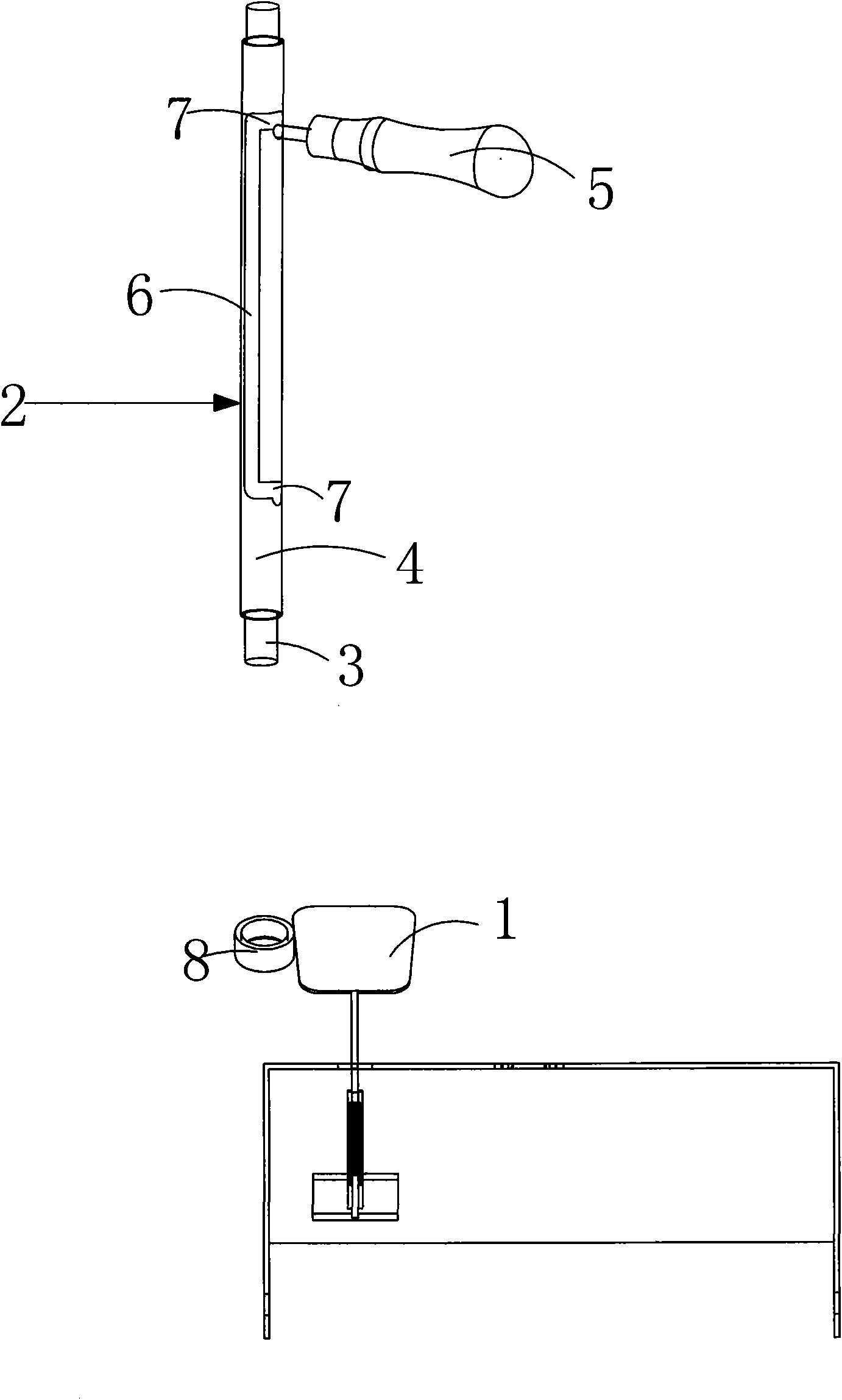
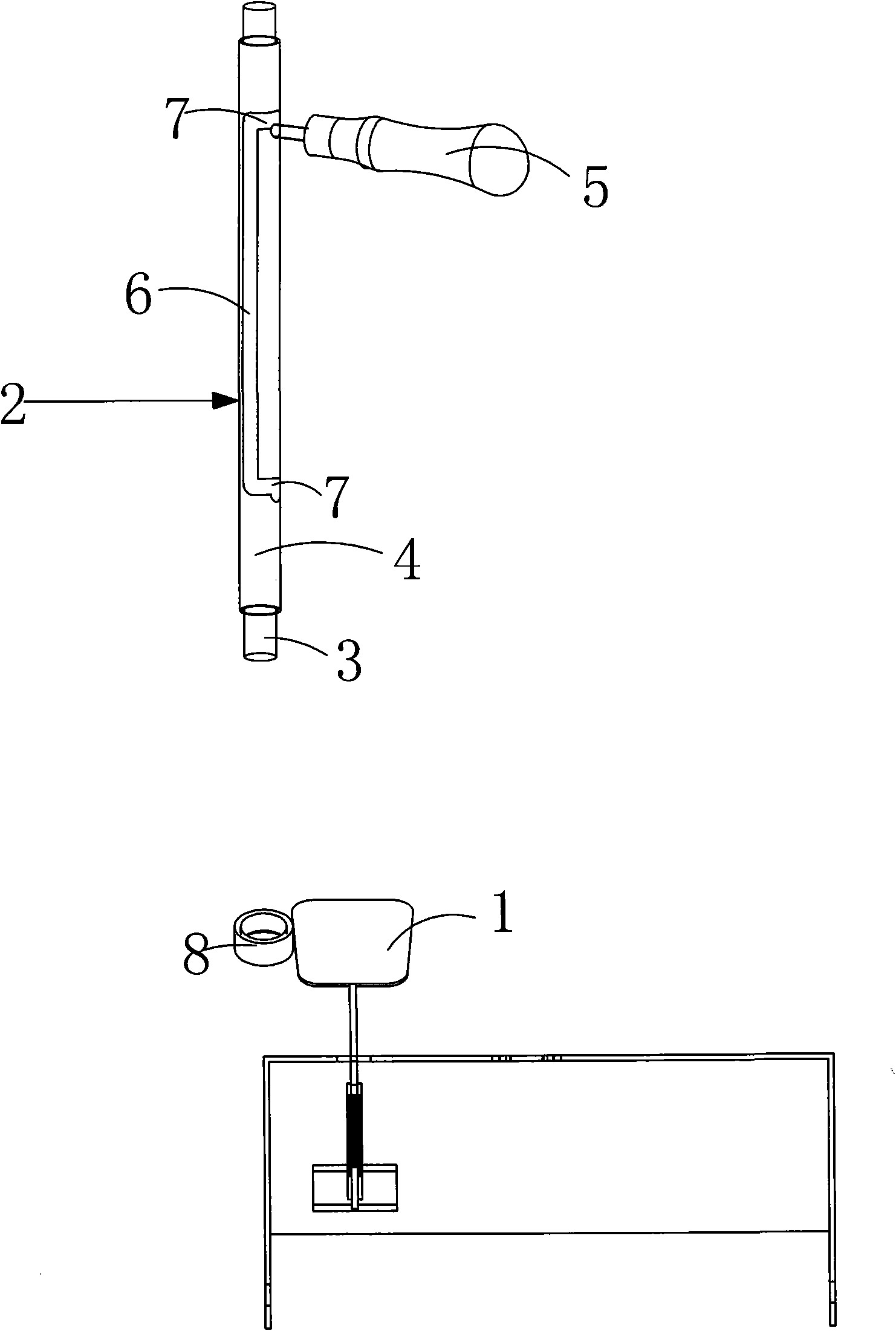
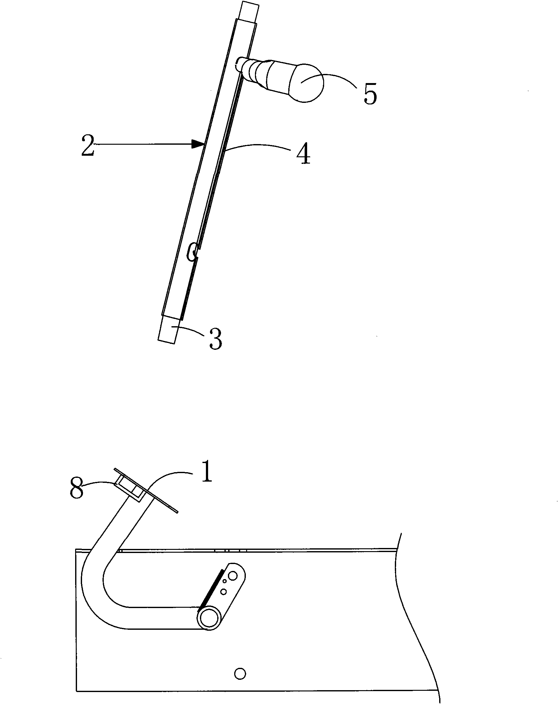
[0012] Embodiment: an improved brake system of a four-wheeled electric pedal vehicle, including a brake pedal 1, is provided with a brake lever 2, and the brake lever 2 is composed of a movable rod 3, a sleeve 4 and a fixed handle 5, with The direction of use is the reference: the position of the sleeve 4 is fixed on the vehicle body above the brake pedal 1, the sleeve 4 is provided with a sliding groove 6, and the upper and lower ends of the sliding groove 6 are respectively provided with a bayonet 7. The movable rod 3 is movably installed in the casing 4, and one end of the fixed handle 5 is movably installed in the sliding groove 6 and is fixedly connected to the movable rod 3. The fixed handle 5 can slide along the sliding groove 6 and can be locked in the sliding In the two bayonet sockets 7 on the groove, when the fixed handle 5 was stuck in the bayonet socket 7 at the lower end of the sliding groove, the lower end of the movable rod 3 could just hold against the brake pe...


PUM


Abstract

The invention discloses an improvement on a brake system of a four-wheel electric / foot-operated dual-mode vehicle, which is provided with a brake clamping rod, wherein the brake clamping rod comprises a moving rod, a sleeve pipe and a fixed handle, the sleeve pipe is positioned in the vehicle body above a brake pedal, the sleeve pipe is provided with a gliding groove, the upper end and the lower end of the sliding groove are respectively provided with a bayonet, the moving rod is movably inserted in the sleeve pipe, one end of the fixed handle is movably inserted in the sliding groove and is fixedly connected with the moving rod, and the fixed handle slides along the sliding groove and can be clamped in the two bayonets of the sliding groove. By combining the brake clamping rod with the brake pedal, people only need to slide the moving rod of the brake clamping rod downwards after the brake pedal is stepped so as to position the moving rod at the bayonet at the lower end of the sliding groove via the fixed handle to enable the lower end of the moving rod to keep pressing the brake pedal without keeping the state of stepping the brake pedal while parking is needed on a sliding slope, thereby realizing simple and reliable operation.

Description

technical field [0001] The invention relates to the field of brake devices, in particular to an improved brake system of an electric scooter. Background technique [0002] With the rapid development of electric bicycles, electric bicycles have gradually replaced ordinary bicycles. Electric bicycles are fast and convenient to ride, and are becoming people's main means of transportation. However, electric bicycles are faster than ordinary bicycles and have two-wheel driving stability. Therefore, it is necessary to seek a new method that can solve the stability and safety of two-wheeled electric vehicles, so that four-wheeled electric vehicles have appeared, and four-wheeled electric vehicles The appearance is close to that of a car, and its shape and operation are similar to a car, but it has two functions of electric and pedal. It becomes a means of transportation and has the nature of leisure and entertainment. [0003] Although the existing four-wheeled electric vehicle is...

Claims


Application Information

Patent Timeline
IPC IPC(8): B62L3/04B62L3/02B62M23/02
Inventor 陈马骕
Owner 得利塑胶工业(昆山)有限公司
Learn More