Pedal lock control device for working vehicle

A work vehicle, locking control technology, applied in the layout of control devices, mechanical control devices, power device control mechanisms, etc., can solve problems such as the inability to release pedal locks

Inactive Publication Date: 2010-08-25
NIHON KENKI CO LTD
View PDF7 Cites 7 Cited by
  • Summary
  • Abstract
  • Description
  • Claims
  • Application Information

AI Technical Summary

Problems solved by technology

However, when the cancel switch malfunctions, the pedal lock cannot be released except when the operation switch is turned off.

Method used


Image

  • Pedal lock control device for working vehicle
  • Pedal lock control device for working vehicle
  • Pedal lock control device for working vehicle

Examples


Embodiment Construction

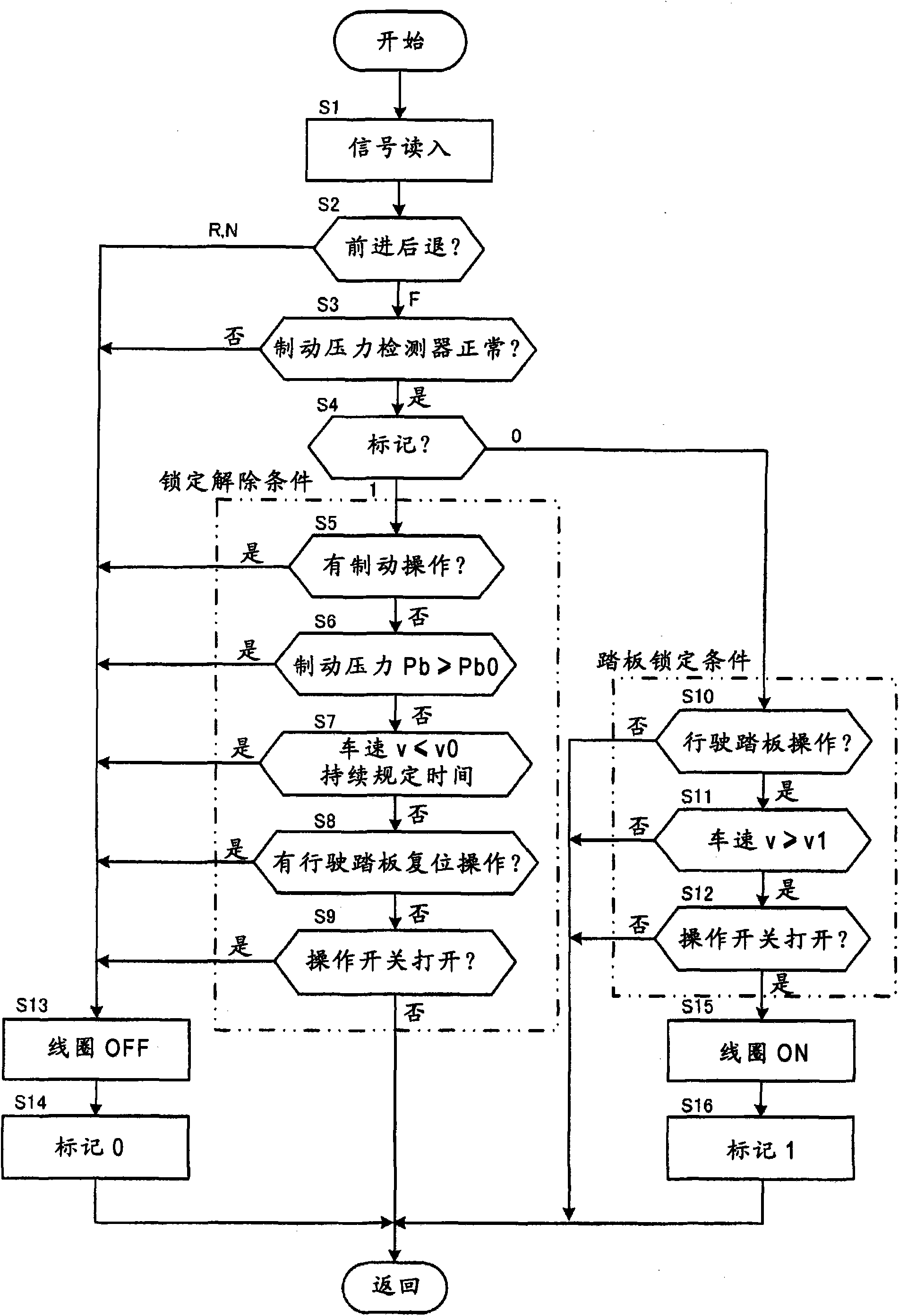
[0019] An embodiment of the present invention will be described below with reference to FIGS. 1 to 4 .

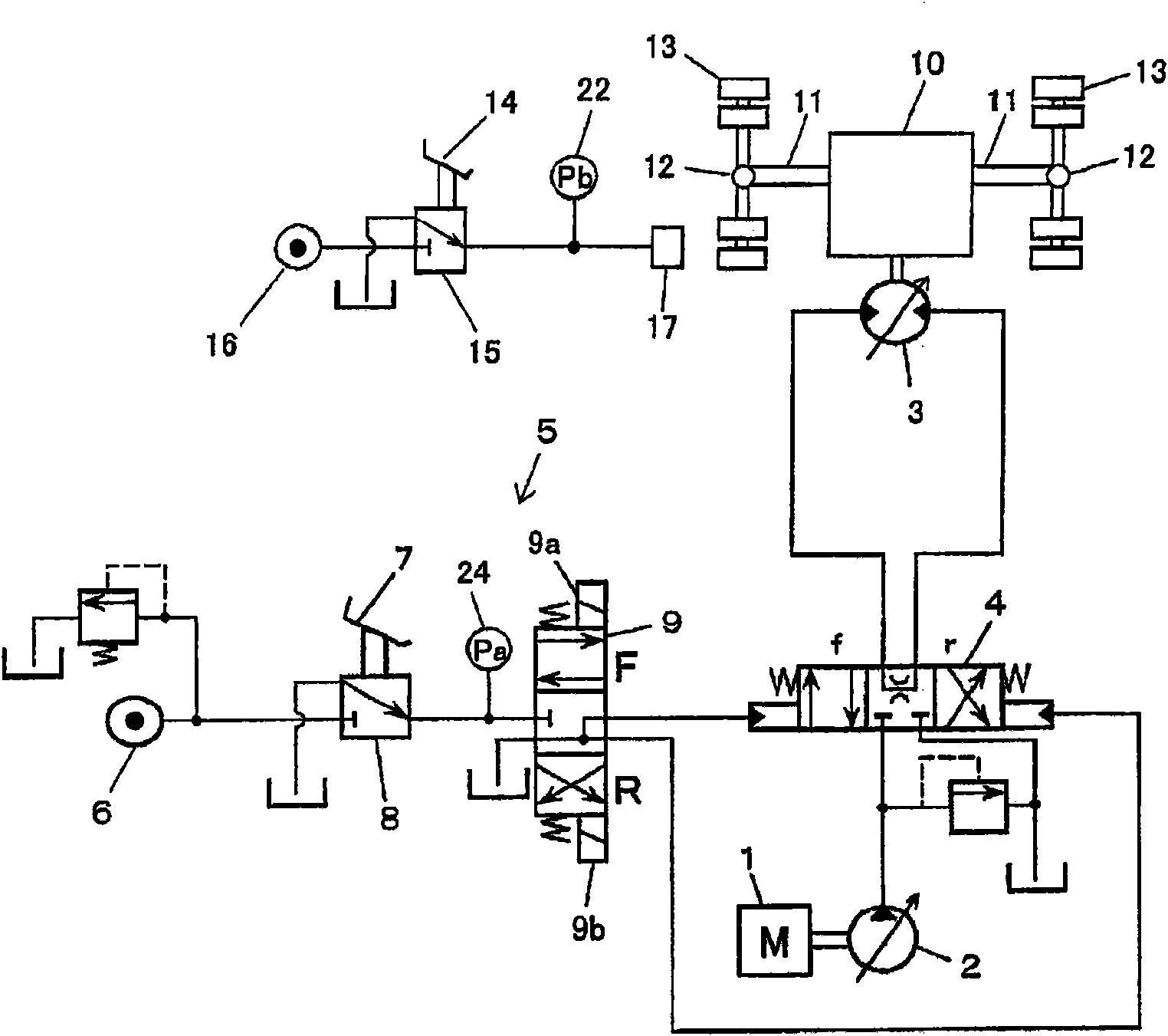
[0020] Fig. 1 is a hydraulic circuit diagram of a work vehicle having a pedal lock control device according to the present embodiment, especially a hydraulic circuit diagram for traveling of a work vehicle equipped with tires such as a wheeled hydraulic excavator and capable of running on a work site or on a general road. .

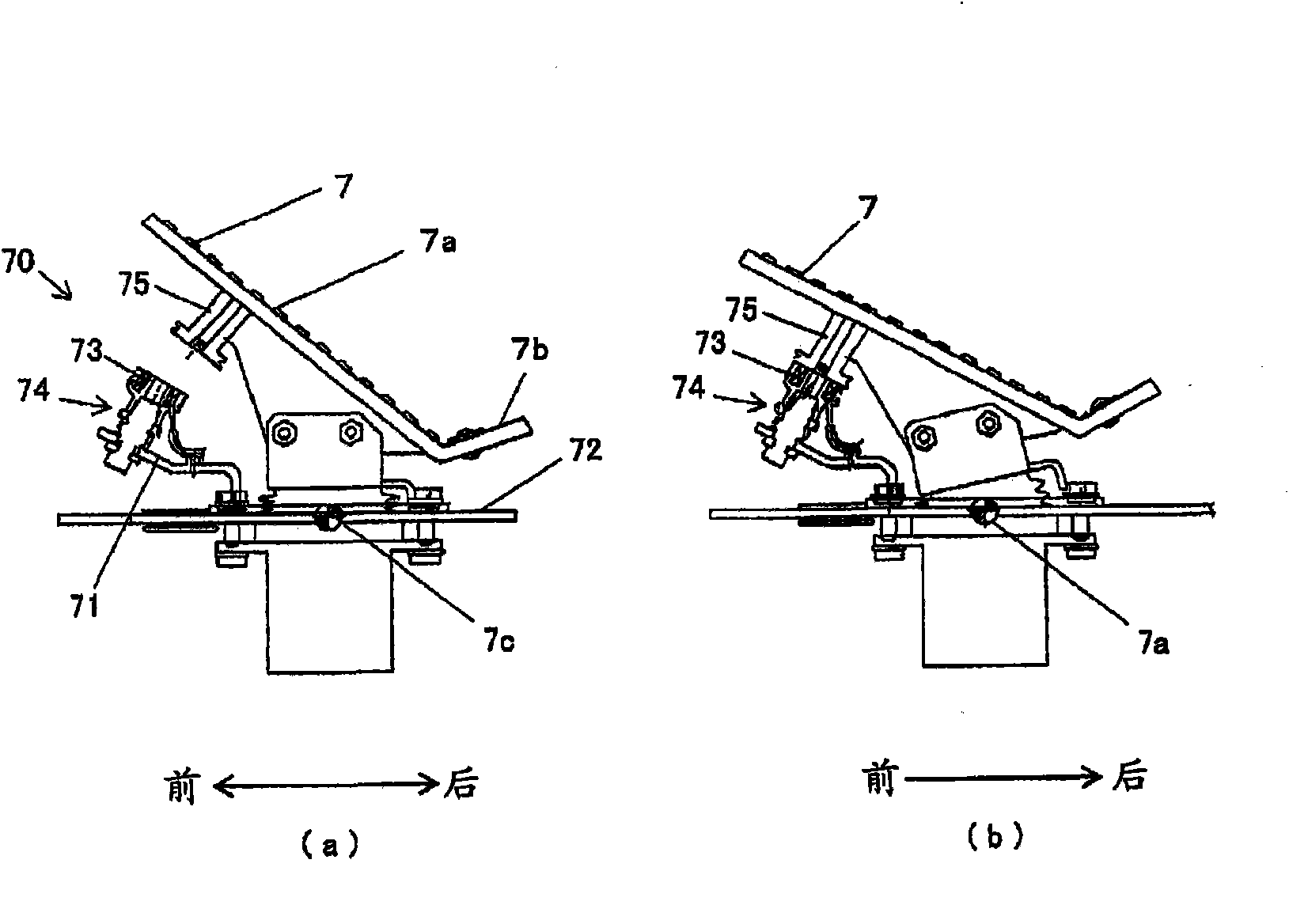
[0021] The hydraulic circuit includes: a hydraulic pump 2 driven by the engine 1, a hydraulic motor 3 driven by hydraulic oil from the hydraulic pump 2, a travel control valve 4 that controls the flow of hydraulic oil from the hydraulic pump 2 to the hydraulic motor 3, and an operating Pilot hydraulic circuit 5 for control valve 4 . The pilot hydraulic circuit 5 has: a pilot hydraulic source 6, a pilot valve 8 that generates a pilot pressure corresponding to the driver's operation amount of the travel pedal 7, and a pilot valve 8 that is activated acc...


PUM


Abstract

A pedal lock control device for a working vehicle has a motor drive device for driving a hydraulic travel motor according to the amount of operation of a travel pedal, a lock device for locking (fixing) the travel pedal to an operated state, an instruction device for instructing, according to operation of the operator, locking of the travel pedal by the lock device and release of the lock, a first detection device for detecting a first signal change generated by lock release operation which is operation reflecting the intention of the operator releasing the lock device and which is operation different from lock release operation by the instruction device, a second detection device for detecting a second signal change different from the first signal change and generated by lock release operation which is operation reflecting the intention of the operator releasing the lock device and which is operation different from lock release operation by the instruction device, and a lock control device for releasing lock of the lock device when at least either of the first and second detection devices detects lock release operation with the travel pedal locked by the lock device.

Description

technical field [0001] The present invention relates to a pedal lock control device for working vehicles such as wheeled hydraulic excavators. Background technique [0002] In such a work vehicle, a device capable of fixing a travel pedal in a depressed state is known (see Patent Document 1). In the device of Patent Document 1, when the operation switch is turned on with the travel pedal depressed, the electromagnet operates, and the travel pedal is locked in the depressed state by magnetic force. Then, when the operation switch is turned off or the brake pedal is operated, the operation of the electromagnet is released, and the pedal lock is released. [0003] Patent Document 1: Japanese Patent Application Laid-Open No. 5-178118 [0004] In the device described in the aforementioned Patent Document 1, depression of the brake pedal is detected by a cancel switch. However, when the cancel switch fails, the pedal lock cannot be released except when the operation switch is t...

Claims


Application Information

Patent Timeline
Patent Type & Authority Applications(China)
IPC IPC(8): B60K26/04B60K20/02E02F9/20
CPCG05G5/06E02F9/2004G05G1/38
Inventor 小高克明佐竹英敏古渡阳一后藤勇树一村和弘
Owner NIHON KENKI CO LTD
Why Eureka
Try Eureka