

Blowing fan
A blower fan and fan blade technology, applied in the field of blower fans that reduce turbulence and increase the overall air intake and output volume, can solve the problems of reducing the overall air output, increasing the overall noise of the blower fan, and affecting the air intake of the blower fan. Achieve the effect of reducing wind shear noise and increasing air intake
- Summary
- Abstract
- Description
- Claims
- Application Information
AI Technical Summary
Problems solved by technology
Method used
Image

Examples
Embodiment Construction
[0029] In order to make the above-mentioned and other objects, features and advantages of the present invention more comprehensible, the preferred embodiments of the present invention are specifically cited below, together with the accompanying drawings, as follows:
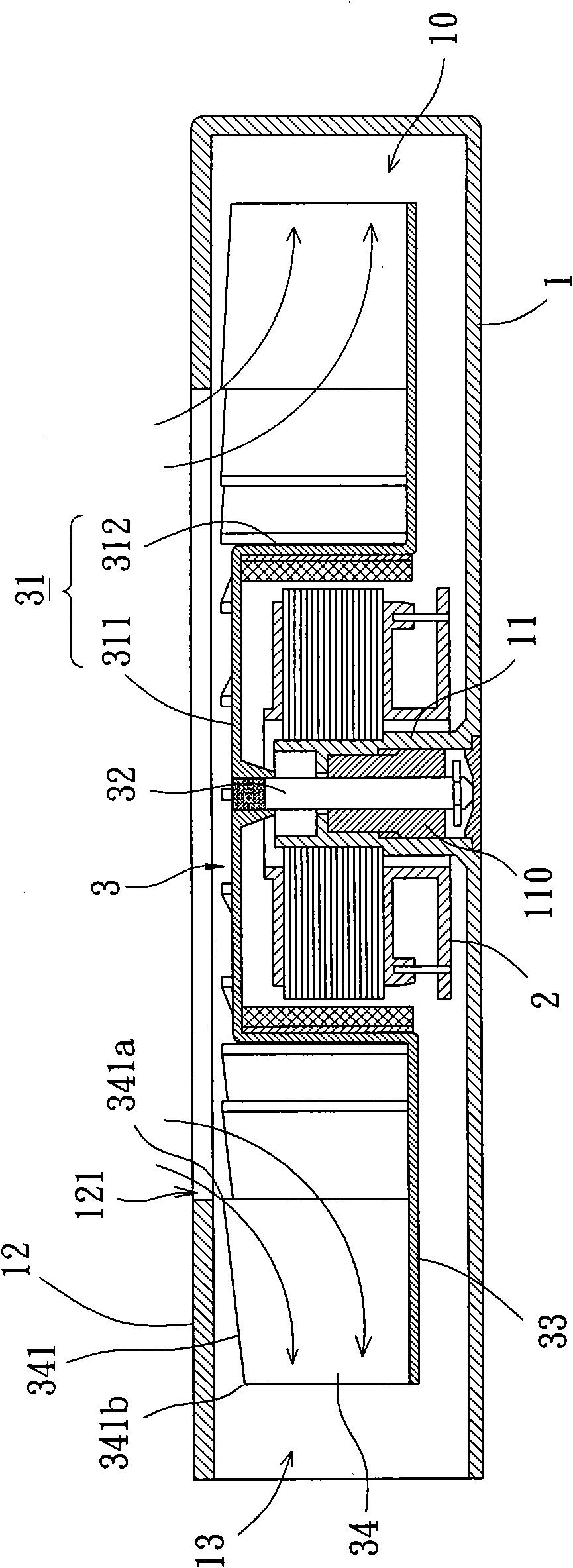
[0030] Please refer to figure 2 As shown, the blower fan according to the first embodiment of the present invention includes a casing 1 , a stator 2 and a fan wheel 3 . in:
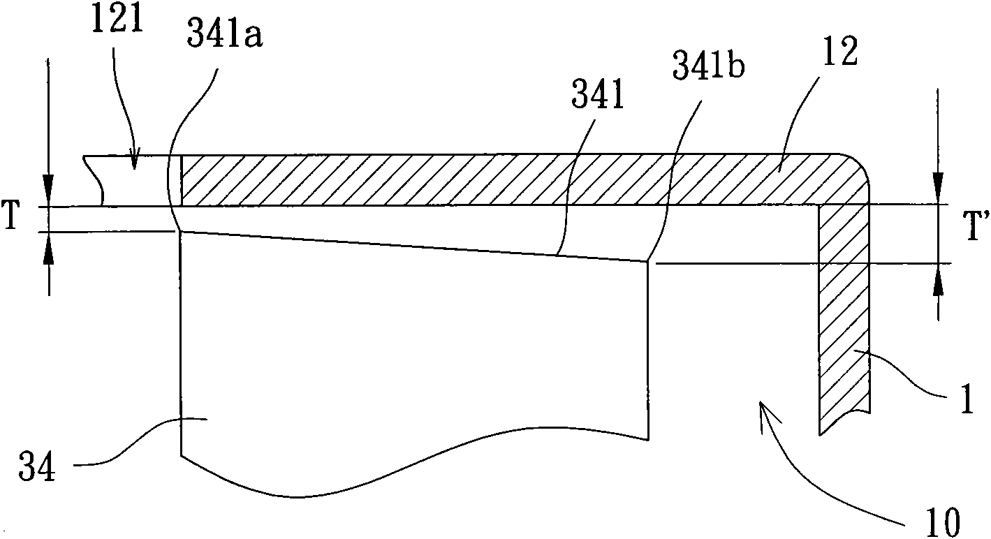
[0031] The housing base 1 has an accommodating space 10, the stator 2 and the fan wheel 3 are both arranged in the accommodating space 10; the accommodating space 10 is provided with a shaft tube 11, and the stator 2 is combined with the shaft tube 11 The outer peripheral surface, and the fan wheel 3 is rotatably arranged in the shaft tube 11 through a bearing 110; the housing base 1 is also provided with a cover plate 12 and an air outlet 13, and the cover plate 12 is assembled on the housing base 1 and the cover plate 12 is provided wit...
PUM
 Abstract
Description
Claims
Application Information