
Method for discriminating cavity structure periphery electromagnetic environment strength

A technology of electromagnetic environment and discrimination method, which is applied in the fields of electromagnetic field characteristics, electrical digital data processing, special data processing applications, etc., and can solve electromagnetic safety problems and other problems

Active Publication Date: 2010-09-01
CHINA SHIP DEV & DESIGN CENT
View PDF6 Cites 5 Cited by
  • Summary
  • Abstract
  • Description
  • Claims
  • Application Information

AI Technical Summary

Problems solved by technology

The cavity has the effect of amplifying the electromagnetic environment, making the electromagnetic environment of the surrounding sensitive equipment exceed the limit value specified in the standard, thereby causing electromagnetic safety issues

Method used


Image

  • Method for discriminating cavity structure periphery electromagnetic environment strength
  • Method for discriminating cavity structure periphery electromagnetic environment strength
  • Method for discriminating cavity structure periphery electromagnetic environment strength

Examples


Embodiment Construction

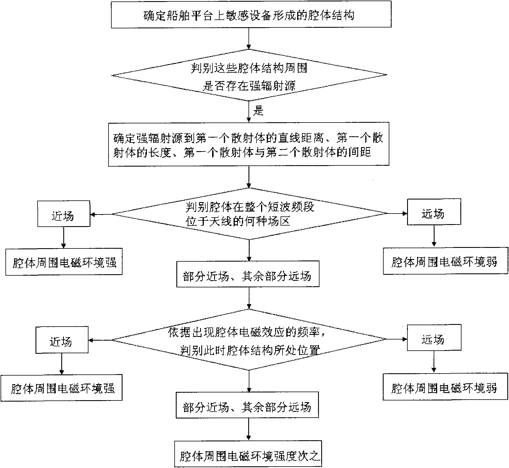
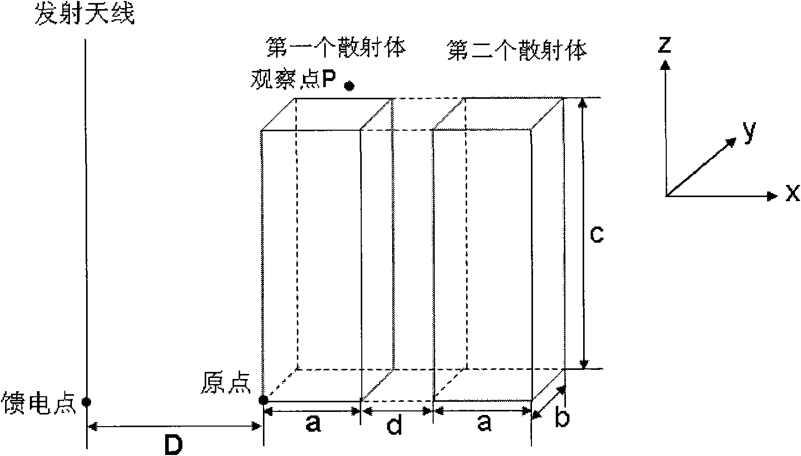
[0044] figure 1 For the flowchart of the present invention, according to the ship design scheme, set up the ship platform in FEKO software, there are radiation antenna and two scatterers on the ship platform, as figure 2 As shown, wherein the length of the first scatterer is a=2.3m, the width b=1.96m, and the height c=6.3m; the distance between the first scatterer and the second scatterer is d=1.2m. The feed point coordinates of the radiating antenna are (-5, 0, 0), that is, the straight-line distance from the radiating antenna to the first scatterer is D=5m. The length of the radiation antenna is L=10m, and the transmitting power is 2000W. The coordinates of the observation point P to be studied are (1.2, 0.98, 6.6).

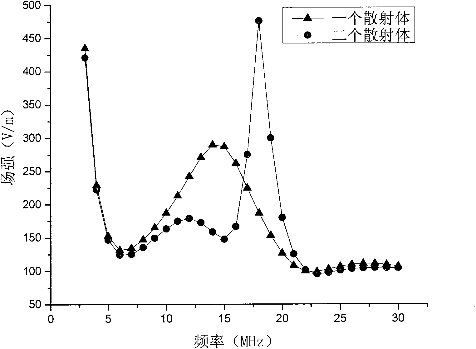
[0045] Assuming that there is only the first scatterer, use FEKO software to calculate and analyze, and obtain the response curve of the electric field intensity of the observation point P with the operating frequency of the radiation antenna (as a reference...


PUM


Abstract

The invention provides a method for discriminating cavity structure periphery electromagnetic environment strength. According to ship design scheme, a ship platform is established in a commercial electromagnetic field simulation software, according to relationship of near far field at the periphery of radiating antenna on the basis of electromagnetic theory, correlation of all the parameters of scatter and the radiating antenna as well as the cavity is constructed, thus primarily judging in which region of the radiating antenna the cavity is located in the shortwave full frequency range of working frequency of radiating antenna; if one part of the cavity is in far field region and the other part is in near field region, the field region of the radiating antenna where the cavity is located is further judged according to frequency of cavity electromagnetic effect. The invention estimates electromagnetic environment strength near cavity structure composed of sensitive devices at the periphery of strong radiation source and provides a reference frame for electromagnetic safety design and electromagnetic protection design of sensitive devices.

Description

technical field [0001] The invention relates to the field of electromagnetic protection, in particular to a method for judging the strength of an electromagnetic environment around a cavity structure. Background technique [0002] On a ship platform, the open space surrounded by scatterers (without a clear closed boundary) can be regarded as a cavity structure. The scatterers that make up the cavity structure are sensitive devices. The cavity has the effect of amplifying the electromagnetic environment, making the electromagnetic environment of the surrounding sensitive equipment exceed the limit value specified in the standard, thereby causing electromagnetic safety issues. [0003] With the increase in the number of sensitive equipment and systems of various carrier equipment, the space of the carrier platform is becoming increasingly crowded, and the problem of electromagnetic hazards caused by the electromagnetic effect of the cavity will become increasingly serious. T...

Claims


Application Information

Patent Timeline
Patent Type & Authority Applications(China)
IPC IPC(8): G01R29/08G06F17/50
Inventor 张崎宋东安侯冬云易学勤黄松高潘晓敏
Owner CHINA SHIP DEV & DESIGN CENT
Learn More