Solar tracking device for solar collector

A solar collector and sun tracking technology, applied in the field of solar energy applications, can solve the problems of complex structure and control of two-dimensional sun tracking devices, and achieve the effect of reducing the overall cost and control complexity

Inactive Publication Date: 2010-09-01
YIKEBO ENERGY TECH SHANGHAI
View PDF0 Cites 16 Cited by
  • Summary
  • Abstract
  • Description
  • Claims
  • Application Information

AI Technical Summary

Problems solved by technology

[0005] The object of the present invention is to provide a sun tracking device for a solar collector, which is

Method used


Image

  • Solar tracking device for solar collector
  • Solar tracking device for solar collector
  • Solar tracking device for solar collector

Examples


Embodiment Construction

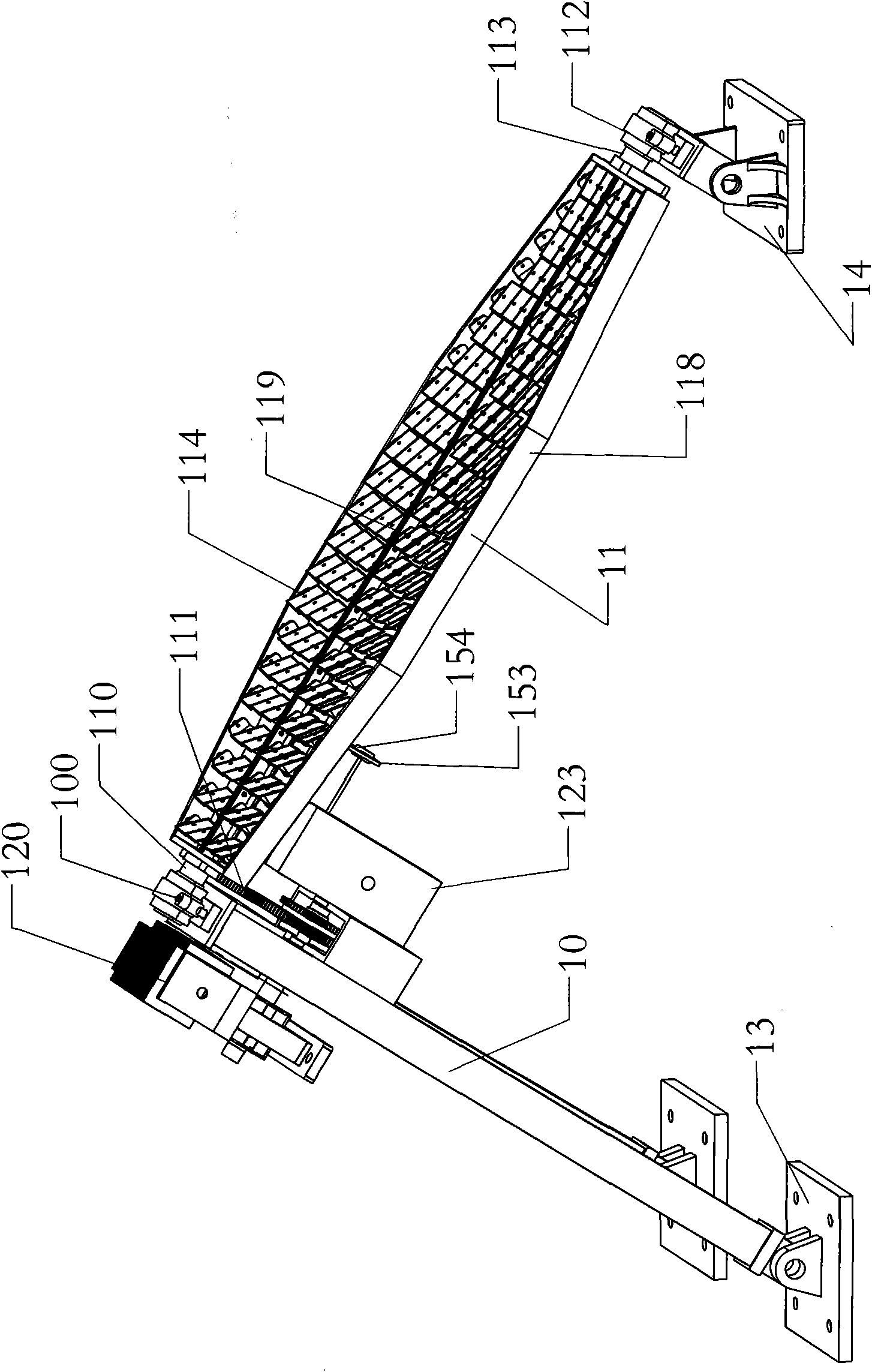
[0031] see figure 1 As shown, it is a structural schematic diagram of a solar collector, which can be applied to a photovoltaic cell system or a concentrating solar thermal application system. The solar collector includes a support frame 10, a panel 11 and a tracking device.

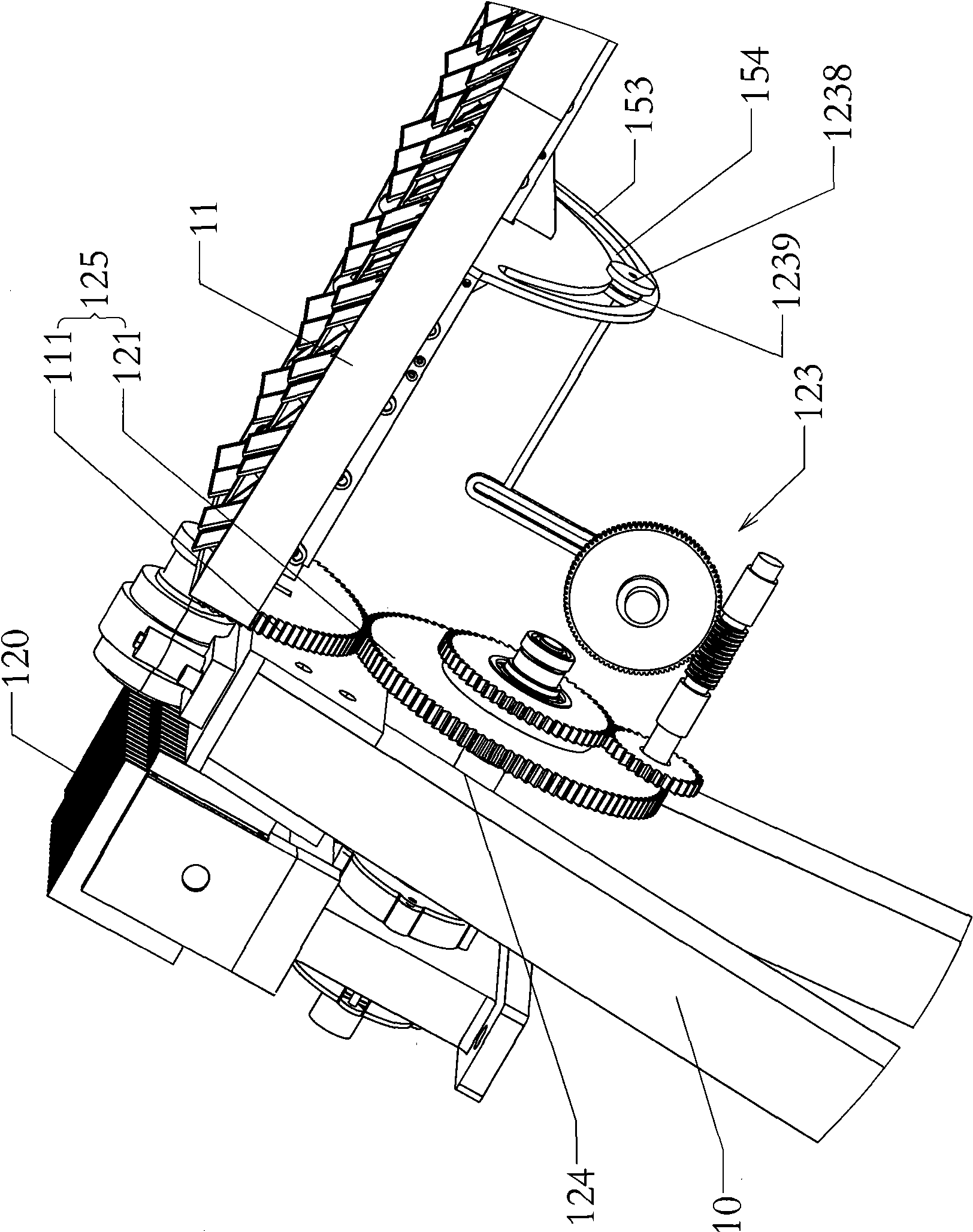
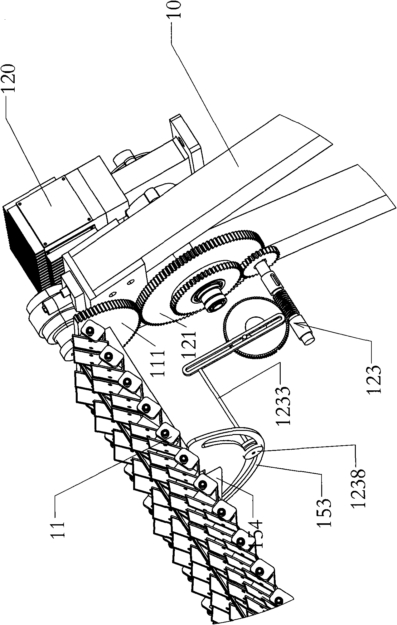
[0032] One end of the support frame 10 is fixed on the ground or other fixed structures through the first base 13, and the other end is provided with a bearing seat 100, and a rolling bearing (not shown) is arranged in the bearing seat 100 to support the first surface of the panel 11. The rotating shaft 110 (details will be described later).

[0033] One end of the panel 11 is supported in the rolling bearing of the bearing seat 100 of the support frame 10 through the first rotating shaft 110, and the first rotating shaft 110 is also provided with a first gear 111, which can rotate according to the direction of the panel 11. The angular range is designed as a half circle or a three-quarter circle. The ...


PUM


Abstract

The invention discloses a solar tracking device for a solar collector, comprising a driving mechanism, a polar axis rotating mechanism which is matched with the driving mechanism to rotate the polar axis of the solar collector, and a season shaft rotating mechanism, wherein, the season shaft rotating mechanism is optionally matched with the polar axis rotating mechanism to drive the season shaft of the solar collector to rotate. In the invention, only one driving mechanism is required to achieve rotation of the polar axis and the season shaft without arranging a single driving mechanism for each shaft, thus reducing the system overall cost and control complexity.

Description

【Technical field】 [0001] The invention belongs to the field of solar energy applications, in particular to a solar tracking device for photovoltaic cell panels or focused solar collectors. 【Background technique】 [0002] Photovoltaic solar panels are widely used in residential or commercial solar applications. Due to the movement of the sun relative to the earth, the sunlight irradiated on the fixed photovoltaic panel has different incident angles at different times of the day or at different times of the year. Such incident light reduces the collection efficiency of the solar panel and reduces the electricity generated by the solar panel. Since the collected solar energy is proportional to the cosine angle, that is, the angle between the incident angle of sunlight and the vertical surface of the solar panel, the losses caused by this effect are known as cosine losses. To increase the efficiency of sunlight collection, solar panels can use a tracking device to maintain a n...

Claims


Application Information

Patent Timeline
IPC IPC(8): H02N6/00G05D3/00H02S20/32
CPCY02E10/50
Inventor 项晓东万荣南施广涛
Owner YIKEBO ENERGY TECH SHANGHAI
Why Eureka
Try Eureka