Coupling device

A technology for connecting devices and connecting parts, which is applied in door/window fittings, roofing, construction, etc. It can solve the problems of disengagement of the window frame from the frame, the inability to determine the reliable locking position of the clip device, etc., and achieve low-cost and reliable mechanical methods Effect

Inactive Publication Date: 2010-09-01
VKR HLDG AS
View PDF1 Cites 0 Cited by
  • Summary
  • Abstract
  • Description
  • Claims
  • Application Information

AI Technical Summary

Problems solved by technology

[0009] Also, the user cannot be sure whether the clip arrangement of the first coupling part to the shaft part is in a securely locked position
If the shaft part has been rotated only a small amount into the locked position, a small amount of rotation in the opposite direction will unintentionally disengage the sash from the frame, which is of course disadvantageous

Method used


Image

  • Coupling device
  • Coupling device
  • Coupling device

Examples


Embodiment Construction

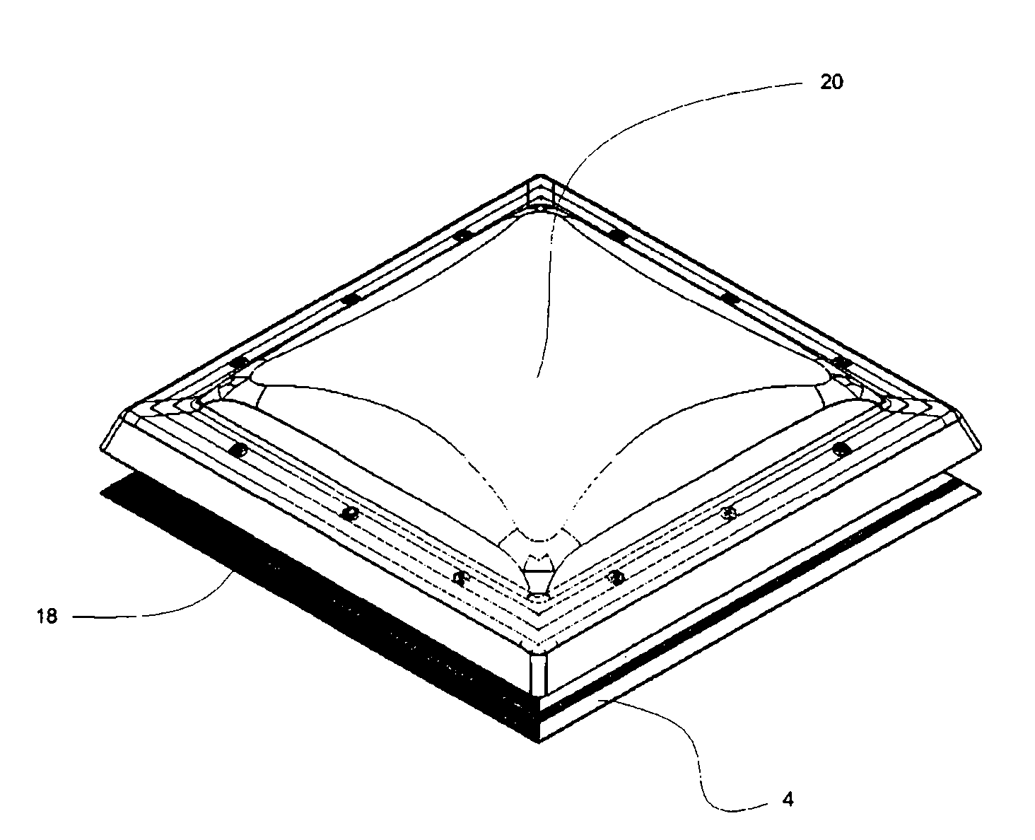
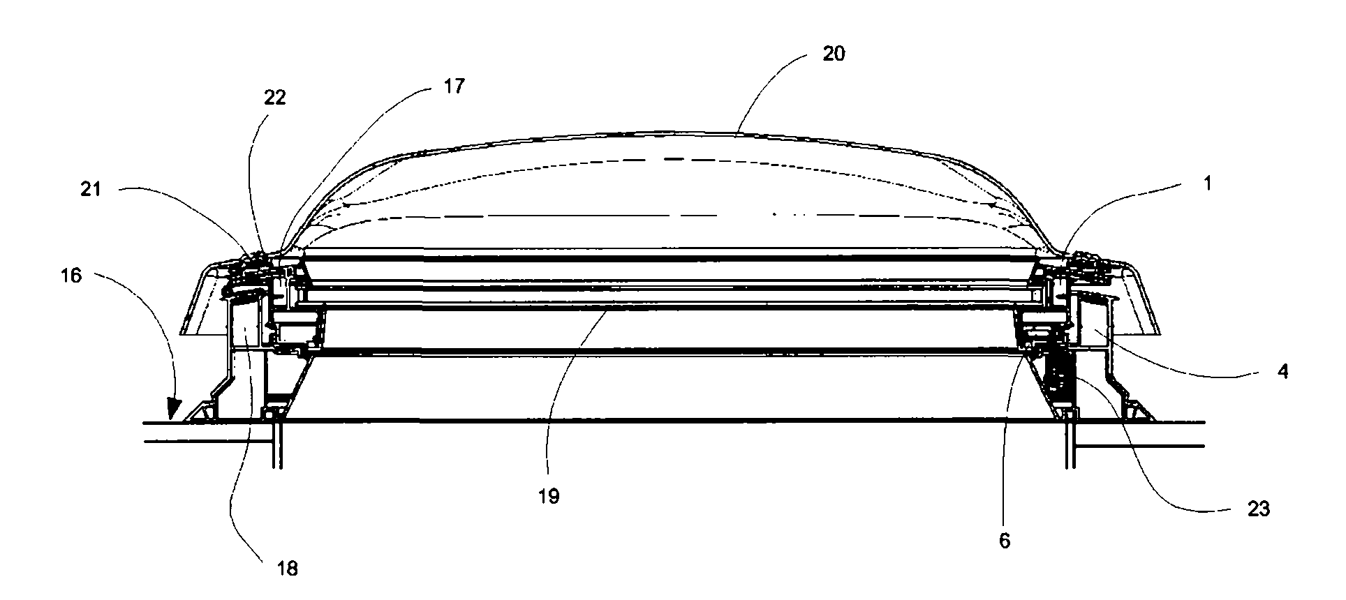
[0033] figure 1 and 2 Different views of a window comprising a first embodiment of a coupling device according to the invention are shown. The window includes a standard Rectangular window section in the form of a top-hung roof skylight (GHL type), which can wrap around along the sides of the window (i.e. figure 2 left) set the horizontal axis to pivot. The window section is mounted in the flat roof 16 and comprises a window frame 17 mounted in a window frame 18, both in the form of an extruded PVC profile. In other embodiments, the frames and sashes may be in the form of extruded aluminum profiles, for example, or they may comprise wooden parts. The window frame 17 encloses the pane 19 of the double glazing with a layer of gas sandwiched therebetween to provide an insulating glazing.

[0034] A cover portion 20 in the form of a domed perspex sheet is attached to the window frame 17 to form a weather shield protecting the window portion. The hood portion 20 includes a ...


PUM


Abstract

A coupling device connects an operator chain of a chain operator to a sash member (1) of a window. The coupling device comprises a securing means (10) adapted to be secured to said sash member (1), a first coupling member (3), which at a first end is designed for connection with said free end of said operator means (2) and at a second end has a mouth (5a) of a cut-out (5), and a second coupling member (6) comprising a shaft member (6a) rotationally secured to said securing means (10). Said shaft member (6a) comprises a connection section (8) with a first transverse dimension (a) correspondingto a width of said mouth (5a) and a second, larger dimension (b) corresponding to a width of said cut-out (5), and rotating means (7) for rotating said shaft member (6a). The coupling device further comprises an indicating means (11) secured to said securing means (10) and abutting said shaft member (6a) such as to indicate to a user, by operation of said rotating means (7), the rotational position of said shaft member (6a).

Description

technical field [0001] The invention relates to a coupling device for connecting an elongate operating device, such as an operating chain of a chain operating mechanism, to a frame part of a window, said coupling device comprising: [0002] fastening means adapted to be fastened to said frame part, [0003] a first coupling part, the first end of which is designed for connection with said free end of said operating device and the second end has a cutout mouth, and [0004] a second coupling part comprising a shaft part rotationally fastened to said fastening means, [0005] The shaft member includes a connecting portion having a first transverse dimension corresponding to the width of the mouth and a second, larger dimension corresponding to the width of the slit, and rotation means for rotating the shaft member. Background technique [0006] Such a coupling device is known from the applicant's European Patent No. 0 740 042 B1. When assembling a window to which such a cou...

Claims


Application Information

Patent Timeline
Patent Type & Authority Applications(China)
IPC IPC(8): E05F15/12
CPCE05F15/123E05Y2201/656E05Y2201/724E05F11/06E05Y2800/73E05Y2900/148E05Y2900/154E04D13/035E05F15/619E05Y2201/214
Inventor 本特·基尔克·延森
Owner VKR HLDG AS
Why Eureka
Try Eureka