Conveying system of digital control processing machine

A conveying system and processing machine technology, which is applied to metal processing machinery parts, metal processing, metal processing equipment, etc., can solve the problems of slow and slow conveying speed of the conveying body 3, and achieve the effect of increasing the allowable rotational speed and increasing the conveying speed.

Active Publication Date: 2012-08-15
DN SOLUTIONS CO LTD
View PDF0 Cites 0 Cited by
  • Summary
  • Abstract
  • Description
  • Claims
  • Application Information

AI Technical Summary

Problems solved by technology

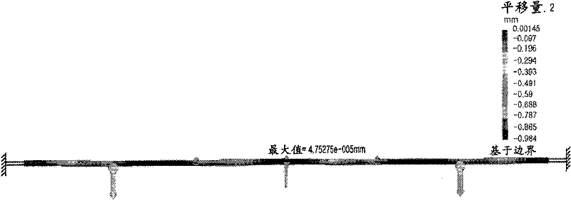
[0009] As an example, a ball screw 12 with a diameter of 100 mm and a distance between the fixed parts at both ends of 10,000 mm has an allowable rotational speed of approximately 200 rpm under normal installation conditions (fixed-fixed support), which is very slow. The rotational speed is so low that the conveying speed of the conveying body 3 becomes slow as a result

Method used


Image

  • Conveying system of digital control processing machine
  • Conveying system of digital control processing machine
  • Conveying system of digital control processing machine

Examples


Embodiment Construction

[0039] The advantages and features of the present invention, as well as the methods for realizing them, will be more clearly understood through the accompanying drawings and the embodiments described in detail below.

[0040] Throughout the specification, the same reference signs refer to the same structural elements.

[0041] Below, refer to image 3 and Figure 7A conveying system of a numerically controlled processing machine according to a first embodiment of the present invention will be described.

[0042] In the attached picture image 3 is an exemplary plan view for explaining a conveying system of a numerically controlled processing machine according to a first embodiment of the present invention, Figure 4 yes image 3 An illustration of the X-X line section.

[0043] Such as image 3 and Figure 4 As shown, according to the conveying system of the numerical control processing machine according to the first embodiment of the present invention, the servo motor ...


PUM


Abstract

The invention relates to a conveying system of a digital control large-scale processing machine, which comprises a ball screw (12) which is arranged on a frame (15) and can rotate driven by a servo motor (11); a nut block (21) which can combine a nut parts combined with the ball screw (12) in the screw thread connection mode with a conveying body (3) to enable the conveying body (3) to move alongthe straight line; a shaft support (20) which is arranged at one side of the frame (15) and is provided with first and second idle rotation rollers (92a, 92b) which can support the ball screw (12) atthe upper side; a descend drive mechanism which enable the shaft support (20) to descend for preventing the collision of the nut block (21) and the shaft support (20), when the nut block (21) passes through the shaft support (20).

Description

technical field [0001] The present invention relates to the conveying system (Transfer subsection of numerical control machine tools), and more specifically, relates to the threaded combination of the nut block and the ball screw through the nut part, and the use of a servo motor to control the rotation of the ball screw, so that the Conveyor system for CNC machining machines that move nut blocks to precise positions. Background technique [0002] Such as figure 1 As shown, generally speaking, the CNC processing machine 1 can be provided with a conveying system 2 on one side of the main body, and a conveying body 3 is placed on the conveying system 2 . [0003] The conveyance system 2 includes, for example, a numerically controlled servo motor 11 , a ball screw 12 rotated by the driving force of the servo motor 11 , and a nut block 14 connected to the ball screw 12 to move linearly. [0004] The nut block 14 is fixed to the conveying body 3 so that the conveying body 3 is ...

Claims


Application Information

Patent Timeline
Patent Type & Authority Patents(China)
IPC IPC(8): B23Q7/00
CPCB23Q1/34B23Q5/268B23Q5/408B23Q5/44B23Q2705/12B23Q2705/14
Inventor 全圭寅
Owner DN SOLUTIONS CO LTD
Why Eureka
Try Eureka