

Vehicle body structure
A body and vehicle technology, which is applied to the superstructure, vehicle components, superstructure sub-assemblies, etc., and can solve problems such as body deformation
- Summary
- Abstract
- Description
- Claims
- Application Information
AI Technical Summary
Problems solved by technology
Method used
Image


Examples
no. 1 approach
[0049] First, through Figure 1 to Figure 24 The first embodiment will be described. In the description below, Figure 1 to Figure 24 Only the right side of the vehicle 1 is shown, but the left side of the vehicle 1 also has the same structure.
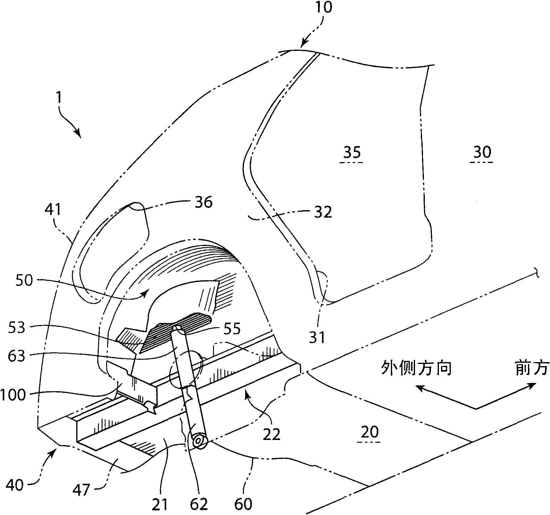
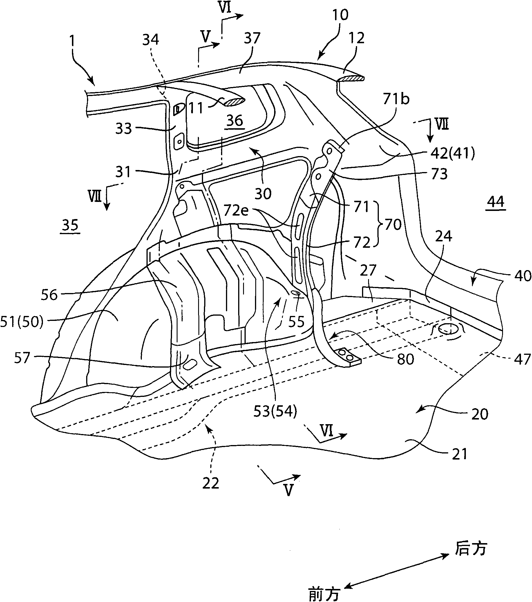
[0050] refer to Figure 1 ~ Figure 3 , the vehicle 1 related to the first embodiment is a vehicle such as a single box car, which has a roof 10 constituting the roof of the vehicle compartment; an underbody part 20 constituting the floor of the vehicle compartment; between the vehicle body side wall portion 30 constituting the side portion of the vehicle body; between the roof 10 and the underbody portion 20, the vehicle body rear wall portion 40 constituting the rear portion of the vehicle body; formed between the underbody portion 20 and the vehicle body side wall portion 30 Between them is a wheel house 50 for accommodating rear wheels (not shown).
[0051] The roof 10 comprises roof reinforcement members 11, 12 (referring to ...
no. 2 approach
[0135] Next, a second embodiment will be described. However, in each of the following embodiments, the same components as those in the first embodiment are given the same reference numerals, and description thereof will be omitted.
[0136] refer to Figure 25 and Figure 26 , in the second embodiment shown in the figure, the upper end portion of the rear side member 22 is provided with a member independent of the main floor 21 , that is, a bottom reinforcement member 28 .
[0137] Also refer to Figure 27 , The bottom reinforcement member 28 is a substantially rectangular plate-shaped member, and its thickness is about twice (1.0 mm) that of the main chassis 21 (for example, 0.5 mm). The outer side of the bottom reinforcement member 28 in the vehicle width direction has a flange 28 a formed along the contour of the lower end portion of the wheel house inner 51 . The flange 28a, as Figure 27 As shown, in a partially undulating state, it extends along the lower end contou...
no. 3 approach
[0145] related to the third embodiment Figure 28 , is a side view showing the rear part of the vehicle body provided with the seat belt. Should Figure 28 In this case, the portion of the inner panel 31 located at the peripheral portion of the rear window opening 36 is removed ( Figure 28 Part B).
[0146] refer to Figure 28 The vehicle body side wall portion 30 of the vehicle 1 is provided with seat belts 150 and 140 respectively corresponding to the second row of seats and the third row of seats (neither of which are shown in the figure) to restrain the occupants seated in these seats.
[0147] The seat belt 140 for the third row of seats is equipped with a seat belt retractor (seat belt retractor) 141 for taking up and accommodating the seat belt 140 at one end thereof, and the seat belt retractor 141 is connected and fixed to the seat belt 140 by a fixing bolt 143. On the bracket part 73. On the other hand, the other end of the seat belt 140 is attached with a lowe...
PUM
 Abstract
Description
Claims
Application Information