Self-lifting load carrying device

A technology of floating device and chain tensioning device, which is applied in hoisting device, hoisting device, etc., can solve the problems of safety, inability to install, and hidden dangers, and achieve the effects of reducing overall weight, flexible and convenient use, and increasing safety factor

Inactive Publication Date: 2010-09-08
WEIFANG WANREN ELECTROMECHANICAL TECH
View PDF7 Cites 13 Cited by
  • Summary
  • Abstract
  • Description
  • Claims
  • Application Information

AI Technical Summary

Problems solved by technology

[0002] At present, there are many load-carrying devices with lifting functions, such as cranes, hoisting machinery, cranes, lifting pulleys (groups), etc., but these lifting load-carrying devices need to be It is used in specific occasions, sometimes limited by environmental conditions, the existing lifting load-carrying device cannot be used
For example, if an air conditioner is installed in a home or office, the outdoor unit is usually manually pulled to the installation position with a rope, and the solar energy is installed on the top of the building, which is also time-consuming and labor-intensive. There are also potential safety hazards, especially when installing outdoor units outside residential buildings with anti-theft windows and on the gable walls of buildings, it is even more difficult to install, or even impossible to install.
The Chinese Invention Patent No. 200710113526.0 discloses a self-elevating load-carrying device. Although the self-elevating load-carrying device can lift heavy objects from the ground to a specified height by itself, the chain cannot be tensioned by itself when it is running. When it is too heavy, it may slip

Method used


Image

  • Self-lifting load carrying device
  • Self-lifting load carrying device
  • Self-lifting load carrying device

Examples


Embodiment Construction

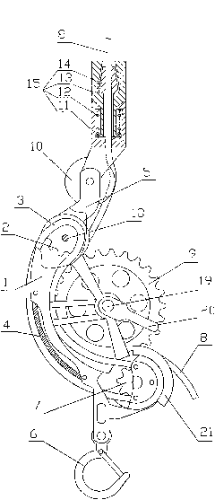
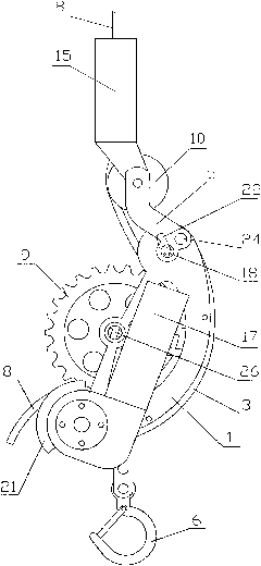
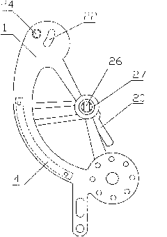
[0022] With reference to accompanying drawing, this self-elevating load-carrying device has support 1, and this support 1 is made up of two symmetrical pieces, and for lightening weight, two support 1 are all curved or arched. Driven double-row sprockets 2 and active double-row sprockets 7 are respectively installed on the top and bottom between the two supports 1, and ring-type double-row chains 3 are installed on the main and driven double-row sprockets. 1. A chain tensioning device 4 is installed on the outside of the driven double-row sprocket connecting heart line, and the crawling double-row sprocket 9 that is arc-engaged with the ring-type double-row chain 3 inner ring sides is installed on its inboard, that is, the ring-type double-row chain The row chain 3 moves circularly around the driven double row sprocket 2 under the drive of the active double row sprocket 7, and the chain tensioner 4 makes the ring type double row chain 3 opposite to the outer double row of the c...


PUM


Abstract

The invention discloses a self-lifting load carrying device, which comprises a support frame, wherein the support frame consists of two symmetrical pieces, the upper part and the bottom part between two pieces of the support frames are respectively provided with driven double-row chain wheels, driving double-row chain wheels, annular double-row chains are arranged on the driving double-row chain wheels and the driven double-row chain wheels, a chain tensioning device is arranged on the outer side of a center connecting line of the driving double-row chain wheels and the driven double-row chain wheels, creeping double-row chain wheels which are in arc-shaped engagement with the inner annular side of the annular double-row chains are arranged on the inside of the center connecting line of the driving double-row chain wheels and the driven double-row chain wheels, arc-shaped grooves are arranged on the creeping double-row chain wheels, a heavy lifting device is arranged at the bottom of the support frame, a motive power device driving the driving double-row chain wheels to rotate is arranged at one side of the support frame, the driven double-row chain wheels are arranged at the upper part between the two pieces of the support frames through a floating device, and the upper part of the floating device is provided with a rope guide wheel. The device can conveniently lift heavy objects to the specified height from the ground, and in addition, the invention has the advantages of difficult slippage, ingenious structure, flexible and convenient use, no limitation by places and environments, safety and high efficiency.

Description

technical field [0001] The invention relates to a loading device with lifting function. Background technique [0002] At present, there are many load-carrying devices with lifting functions, such as cranes, hoisting machinery, cranes, lifting pulleys (sets), etc., but these lifting load-carrying devices need to be used in specific occasions, and sometimes are limited by environmental conditions. The device becomes unusable. For example, if an air conditioner is installed in a home or office, the outdoor unit is usually manually pulled to the installation position with a rope, and the solar energy is installed on the top of the building, which is also time-consuming and labor-intensive. There are potential safety hazards again, especially outside the residential building where anti-theft windows have been installed and outdoor units are installed on the gable of the building, it is difficult to install, or even impossible to install. The Chinese Invention Patent No. 2007101...

Claims


Application Information

Patent Timeline
Patent Type & Authority Applications(China)
IPC IPC(8): B66F19/00
Inventor 赵修和赵丹
Owner WEIFANG WANREN ELECTROMECHANICAL TECH
Why Eureka
Try Eureka