
Construction method for dividing unit to prefabricate bearing bent frame

A construction method and unit-by-unit technology, which is applied in the field of unit-by-unit prefabricated load-bearing bent frame construction, can solve problems such as high construction safety risks, low work efficiency, and potential safety hazards, and achieve the effects of eliminating safety risks and shortening the straight-line construction period

Inactive Publication Date: 2011-06-29
CHINA GEZHOUBA GROUP CO LTD +1
View PDF0 Cites 0 Cited by
  • Summary
  • Abstract
  • Description
  • Claims
  • Application Information

AI Technical Summary

Problems solved by technology

When adopting this assembling method of erecting load-bearing bent racks in situ, since the up and down cross operations cannot be performed, other work on the adjacent working surface of this part must be stopped for a long time during the erection period, which directly affects the construction period of the adjacent operation items; The lattice column is used as the load-bearing column, but when the lattice column is hoisted, the construction personnel need to perform temporary reinforcement on the component in the air and under the hook, which is time-consuming and labor-intensive, and has potential safety hazards
This traditional load-bearing bent frame construction method has low work efficiency, takes a long straight line construction period, and has extremely high construction safety risks, especially in the construction process of the high-altitude, large-span, and large-capacity formwork support system. The weight of the pieces and the large input of one-time consumable materials make it impossible to assemble commercialized assemblies. The erection of support systems such as load-bearing bent frames or bent frame columns will take a relatively long straight-line construction period, and the existing Construction safety risks are more prominent

Method used


Image

  • Construction method for dividing unit to prefabricate bearing bent frame
  • Construction method for dividing unit to prefabricate bearing bent frame
  • Construction method for dividing unit to prefabricate bearing bent frame

Examples


Embodiment

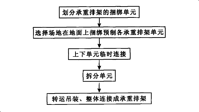
[0023] Example: such as figure 1 Among them, the sub-unit prefabricated load-bearing bent frame construction method includes the following steps:

[0024] 1) Divide each load-bearing bent unit of the load-bearing bent rack;

[0025] 2) Select a site to bind and prefabricate each load-bearing bent unit on the ground;

[0026] 3) The upper and lower units are temporarily connected;

[0027] 4), split unit;

[0028] 5), transfer hoisting, the overall connection into a load-bearing bent frame.

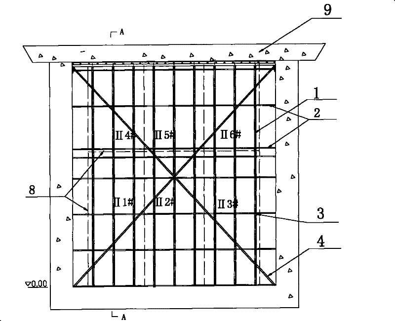
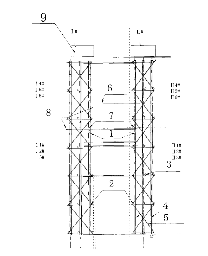
[0029] The load-bearing bent unit is the smallest unit for hoisting. The principle of unit division is: under the premise of meeting the working performance of the equipment lifting the unit, the requirements of the transfer tool and the road for the unit length, width and weight, the total number of units is the least; The unit specifications and shapes should be the same as possible. Such as figure 2 with image 3 In this embodiment, according to the unit splitting line 8, it is ...


PUM


Abstract

The invention discloses a construction method for dividing a unit to prefabricate a bearing bent frame, comprising the following steps of: dividing a binding unit of the bearing bent frame; selecting a field to bind and prefabricate each bearing bent frame units on the ground; temporarily connecting an upper unit and a lower unit; detaching the units; and transferring and hanging the units and integrally connecting the units to be a bearing bent frame. The construction method for dividing the unit to prefabricate the bearing bent frame converts the vast majority of high-altitude operations into flat ground operations to eliminate the safe risk that the part of structures adopt the traditional construction method of the high-altitude operation, changes the crossing operation on the traditional procedure into the parallel operation and converts the in-situ operation into the ex-situ advanced prefab so as to shorten the large quantity of linear work periods, and enables construction enterprises to manufacture tall bearing frames by fully utilizing existing materials.

Description

technical field [0001] The invention relates to a construction method for making and installing a load-bearing bent frame for building construction, in particular to a construction method for sub-unit prefabricated load-bearing bent frame under the environment of large span, high height and large bearing capacity. Background technique [0002] At present, the widely used erection and installation method of various load-bearing bent frames in building construction is the root-by-root assembly method of bent frame members, that is, the prepared steel pipe or angle steel lattice frame, steel bar lattice frame, steel pipe lattice frame, etc. are placed on them. The position of use is lengthened row by row, and finally the load-bearing structure required by the design structure is formed. The bowl-shaped commercial scaffolding that has appeared in recent years still adopts the construction method of assembling in situ at the construction site. When adopting this assembling metho...

Claims


Application Information

Patent Timeline
Patent Type & Authority Patents(China)
IPC IPC(8): E04G21/14
Inventor 黄静
Owner CHINA GEZHOUBA GROUP CO LTD
Learn More