Hydropower station bank slope and stilling pool combined energy dissipation method

A technology for stilling pools and hydropower stations, applied in water conservancy projects, coastline protection, marine engineering and other directions, can solve the problems of insufficient space for building layout, long construction of protective tanks, high engineering cost, and achieve good energy dissipation effect, river bank slope. Stable, good water surface flow

Inactive Publication Date: 2010-09-15
CHONGQING JIAOTONG UNIVERSITY
View PDF2 Cites 9 Cited by
  • Summary
  • Abstract
  • Description
  • Claims
  • Application Information

AI Technical Summary

Problems solved by technology

Although the deflecting flow energy dissipation has the advantages of simple structure, can effectively control the position, range and flow distribution of the jet falling into the downstream river bed, has strong adaptability to tailwater amplitude change, and has the advantages of small engineering quantity, it has become the most widely used energy dissipation method in engineering. , but in engineering practice it also has the following disadvantages: the downstream local erosion problem is more serious, there are more accumulations, and the tail water fluctuation and atomization are relatively large
The method of building stilling pools for energy dissipation often has the advantages of stable flow, good energy dissipation effect, strong adaptability to geological conditions and tailwater amplitude, and small water atomization. However, building water conservancy projects in mountainous rivers During the project, according to the aforementioned characteristics of mountainous rivers, there are often problems such as long building aprons, insufficient space for building layout, large excavation volume of earthwork and concrete volume, and high project cost.

Method used


Image

  • Hydropower station bank slope and stilling pool combined energy dissipation method
  • Hydropower station bank slope and stilling pool combined energy dissipation method
  • Hydropower station bank slope and stilling pool combined energy dissipation method

Examples


Embodiment Construction

[0027] The present invention will be further described in detail below in conjunction with the accompanying drawings and specific embodiments.

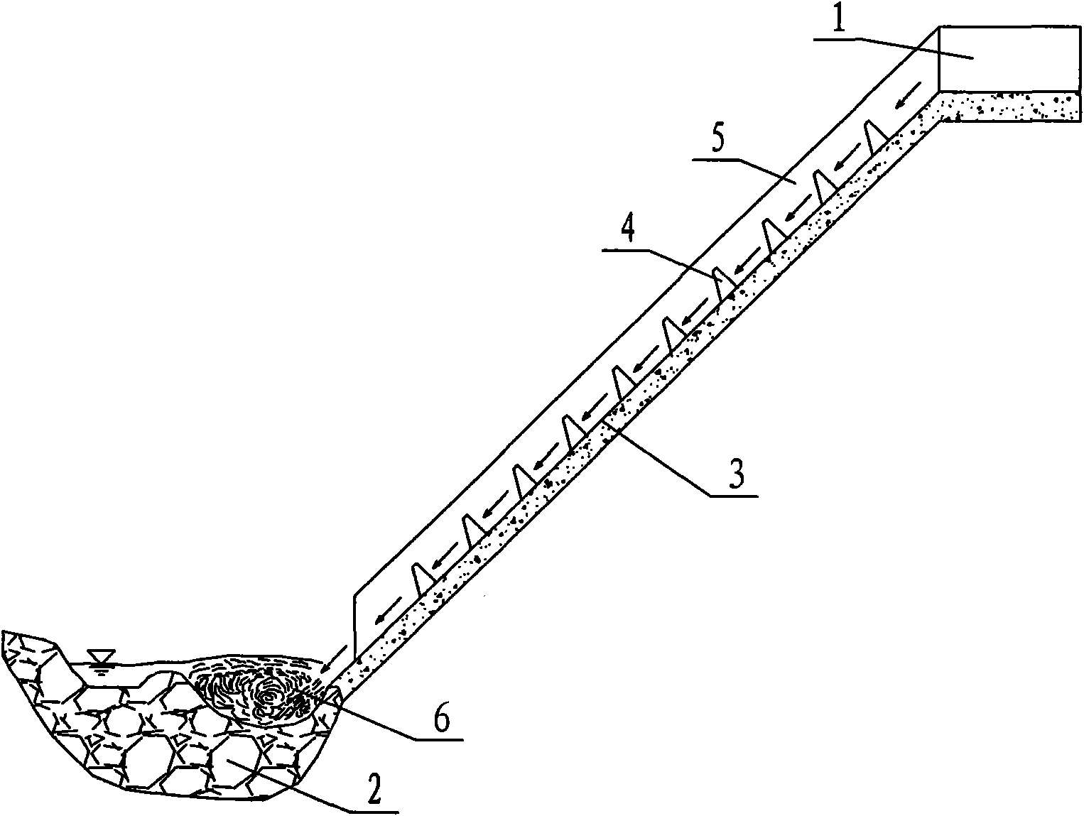
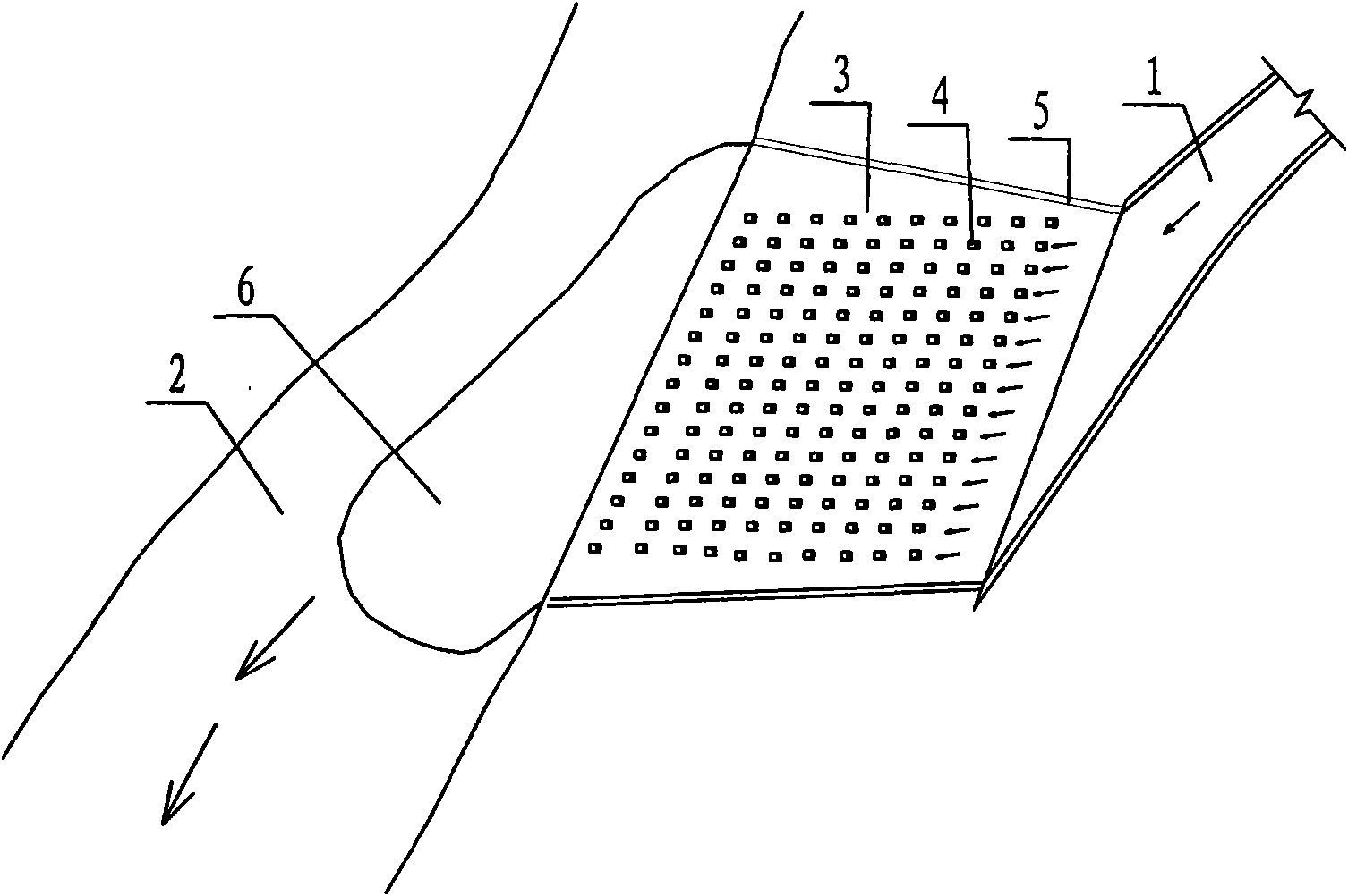
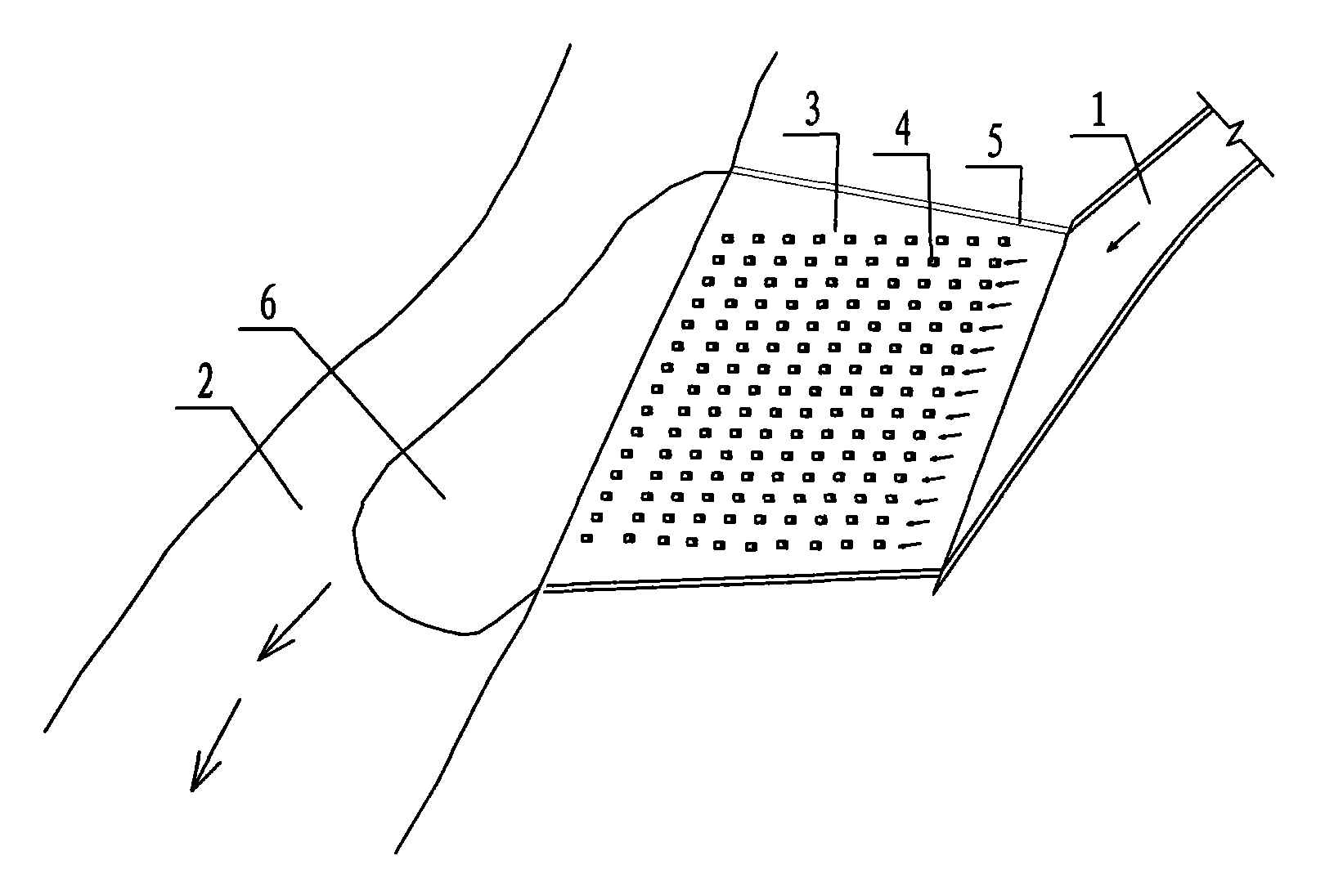
[0028] A combined energy dissipation method for a hydropower station bank slope and a natural stilling basin, which is implemented as follows figure 1 and figure 2 As shown, a trapezoidal bank slope 3 with a slope of less than 70° is set below the outlet of the spillway of the hydropower station. The bank slope 3 is formed by a flat lining of a natural bank slope. After the water flows down the bank slope 3 to reduce the single-width flow rate, a natural stilling pool 6 is washed out at the edge of the downstream riverbed 2, and the water flowing out of the spillway outlet flows through the bank slope 3 and the natural stilling pool 6 after combined energy dissipation. Discharge along the river bed 2. During implementation, multiple rows of stilling piers 4 are horizontally arranged on the bank slope. The stilling piers 4 are pier-...


PUM


Abstract

The invention discloses a hydropower station bank slope and stilling pool combined energy dissipation method, which is characterized in that: a trapezoidal bank slope with a gradient of less than 70 DEG is built below a water outlet of a spillway of a hydropower station; the lower end of the bank slope is jointed with a river bed; a water flow passing through the water outlet of the spillway flows down from the bank slope to reduce unit discharge and wash a natural stilling pool on the edge of the river bed; and after the energy of the water flow is dissipated by the bank slope and the natural stilling pool jointly, the water flow passing through the water outlet of the spillway is discharged along the river bed. In the method, the bank slope can be built by leveling and lining a natural bank slope and made into a trapezoid with a narrow upside and a wide downside; while the water flow passing through the water outlet of the spillway is discharged downward along with the trapezoidal bank slope, the unit discharge of the water flow discharged downward is reduced; the water flow discharged downward washing a downstream river bed close to the edge of the bank slope to make a scour pit; and the scour pit serving as a natural stilling pool allows the water flow discharged downward to make a jump so as to dissipate the energy of the water flow. The method can produce desirable energy dissipation effect and can effectively save the space occupation of buildings.

Description

technical field [0001] The invention relates to the field of water conservancy engineering, in particular to a combined energy dissipation method of a bank slope of a hydropower station and a natural stilling pool. Background technique [0002] At present, with the gradual development of hydropower resources in mountainous rivers in my country, the development of hydropower engineering construction in China has entered a climax stage, especially in the western mountainous areas where a large number of small and medium hydropower stations have been built. The water flow in natural rivers is generally slow flow, and the single-width discharge is evenly distributed along the river width direction. However, when discharge structures such as dams and sluices are built in the river channel, the flow conditions in the river channel have changed greatly. destructive power. If this problem is not solved in actual engineering, it will not only cause serious erosion and siltation in ...

Claims


Application Information

Patent Timeline
Patent Type & Authority Applications(China)
IPC IPC(8): E02B8/06
Inventor 杨胜发张艾文胡鹏飞金龙许俊杰刘汉天
Owner CHONGQING JIAOTONG UNIVERSITY
Why Eureka
Try Eureka