Optical encoder
An optical and encoder technology, applied in the field of optical encoders, can solve problems such as difficulty in miniaturization
- Summary
- Abstract
- Description
- Claims
- Application Information
AI Technical Summary
Problems solved by technology
Method used
Image
Examples
no. 1 Embodiment approach
[0059] (Structure of the first embodiment)
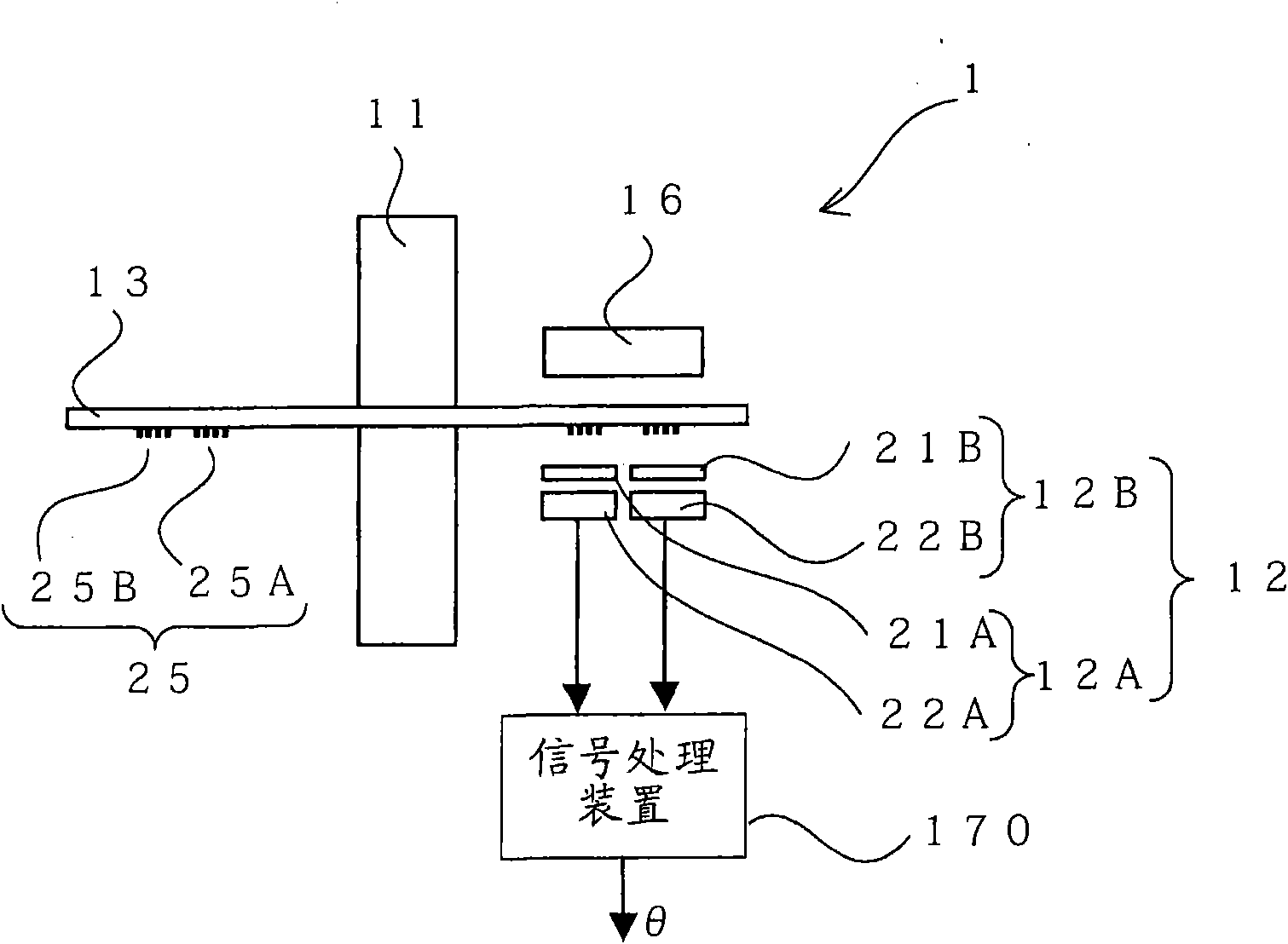
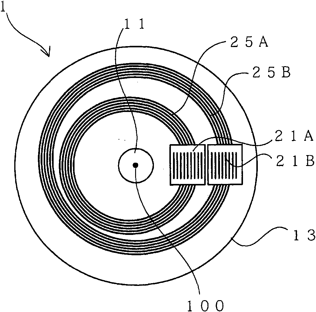
[0060] figure 1 It is a side view showing the optical encoder according to the first embodiment of the present invention, figure 2 is the floor plan. in, figure 2 The floor plan is viewed from the underside of the paper figure 1 And the obtained figure.
[0061] Such as figure 1 and figure 2 As shown, the optical encoder 1 of the present embodiment is roughly divided and includes: a rotating shaft 11 , a turntable 13 , an annular slit 25 , a light source 16 , a detection unit 12 , and a signal processing device 170 .
[0062] One end of the rotating shaft 11 is connected to a rotating body (not shown) whose rotation angle is to be measured, and the rotating shaft 11 rotates around a rotation center 100 in the longitudinal direction of the rotating shaft 11 as the rotating body rotates.
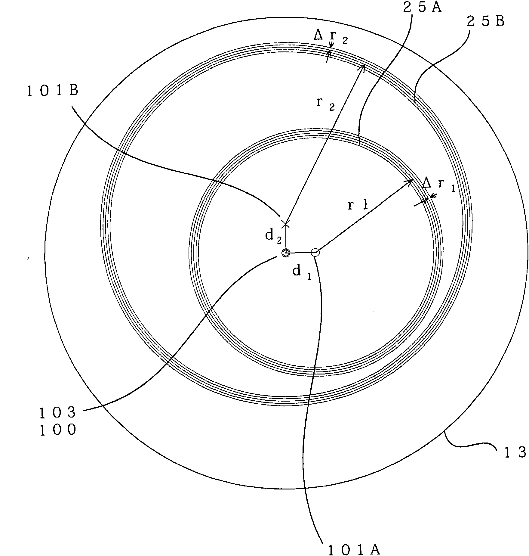
[0063] The turntable 13 is connected to the rotation shaft 11 and formed to be rotatable around the rotation center 100 as the rotation s...
no. 2 Embodiment approach
[0136] (Structure of the second embodiment)
[0137] Figure 15 It is a side view showing the optical encoder according to the second embodiment of the present invention.
[0138] The main difference from the first embodiment lies in the configuration of the reflective optical system to which the principle of three gratings is applied. In addition, since the signal processing part 17 of this embodiment can employ|adopt the same structure as the said 1st Embodiment or the 3rd Embodiment mentioned later, it is abbreviate|omitted for convenience of description.
[0139] In the optical encoder 2 of this embodiment, the light source 16 is arranged on the same surface side as the first light receiving element 22A and the second light receiving element 22B of the turntable 13, and the light source slit 40 is arranged on the optical path of the light source 16. , and instead of the first fixed slit 21A and the second fixed slit 21B, the first index slit 41A and the second index slit...
no. 3 Embodiment approach
[0168] (Structure of the third embodiment)
[0169] Figure 21 It is a side view showing an optical encoder according to a third embodiment of the present invention, Figure 22 is the floor plan. This embodiment can solve the above-mentioned problems. in, Figure 22 The floor plan is viewed from the underside of the paper Figure 21 And the obtained figure. Components that are the same as those of the encoder of the first embodiment are denoted by the same reference numerals, and description thereof will be omitted.
[0170] Such as Figure 21 As shown, the optical encoder 3 of the present embodiment includes a third annular slit 25C and a third detection unit 12C in addition to the configuration of the encoder 1 of the first embodiment.
[0171] The third annular slit 25C has a plurality of concentric circular slit patterns similarly to the first annular slit 25A and the second annular slit 25B. On the other hand, the third annular slit 25C is formed such that the cente...
PUM
 Abstract
Description
Claims
Application Information
 - R&D
- Intellectual Property
- Life Sciences
- Materials
- Tech Scout
- Unparalleled Data Quality
- Higher Quality Content
- 60% Fewer Hallucinations
Browse by: Latest US Patents, China's latest patents, Technical Efficacy Thesaurus, Application Domain, Technology Topic, Popular Technical Reports.
© 2025 PatSnap. All rights reserved.Legal|Privacy policy|Modern Slavery Act Transparency Statement|Sitemap|About US| Contact US: help@patsnap.com


