
Discharge circuit of UPS (Uninterrupted Power Supply) battery

A battery discharge and circuit technology, applied to battery circuit devices, circuit devices, collectors, etc., can solve the problems of low circuit utilization and high cost of the whole machine, and achieve high circuit utilization, simple control, and easy implementation

Active Publication Date: 2010-09-15
EMERSON NETWORK POWER CO LTD
View PDF0 Cites 2 Cited by
  • Summary
  • Abstract
  • Description
  • Claims
  • Application Information

AI Technical Summary

Problems solved by technology

[0005] The technical problem to be solved by the present invention is to provide a UPS battery with low cost, simple control and easy implementation, aiming at the defects of the prior art UPS battery discharge circuit, such as the low utilization rate of the battery connection mode circuit and the relatively high cost of the whole machine. discharge circuit

Method used


Image

  • Discharge circuit of UPS (Uninterrupted Power Supply) battery
  • Discharge circuit of UPS (Uninterrupted Power Supply) battery
  • Discharge circuit of UPS (Uninterrupted Power Supply) battery

Examples


Embodiment Construction

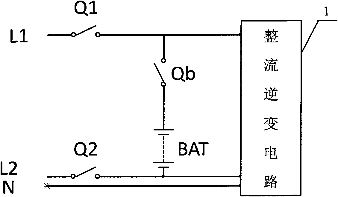
[0016] Such as image 3 As shown, in an embodiment of the UPS battery discharge circuit of the present invention, it includes a battery pack BAT, a rectification and inverter circuit 1, a first mains input live wire L1, a second mains input live wire L2, a mains input zero line N, the first switch Q1, the second switch Q2 and the third switch Qb. The first mains input live wire L1 and the mains second input live wire L2 have the same amplitude and frequency. If the input mains power is 3-phase power, the phase difference between the first mains input live wire and the second mains input live wire is 120 If the input mains is 2-phase power, the phase difference between the first mains input live wire and the second mains input live wire is 180 degrees.

[0017] One end of the battery pack BAT is connected to the first input live wire L1 of the mains power through the third switch Qb, and the other end is connected to the second input live wire L2 of the mains power; one end of...


PUM


Abstract

The invention relates to a discharge circuit of a UPS (Uninterrupted Power Supply) battery, comprising a battery pack, a rectification inverter circuit, a first commercial power input live wire, a second commercial power input live wire, a commercial power input zero line, a first switch, a second switch and a third switch, wherein one end of the battery pack is connected with the first commercial power input live wire by the third switch, the other end of the battery pack is connected with the second commercial power input live wire, the first commercial power input live wire is connected with the rectification inverter circuit by the first switch, the second commercial power input live wire is connected with the rectification inverter circuit by the second switch, and the commercial power input zero line is connected with the rectification inverter circuit. The battery group is hung between the two commercial power input live wires, is not in directly contact with the commercial power input zero line, does not need more batteries, has higher circuit utilization rate and lower cost and is simple to control.

Description

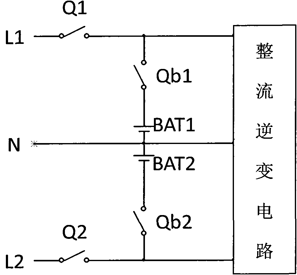
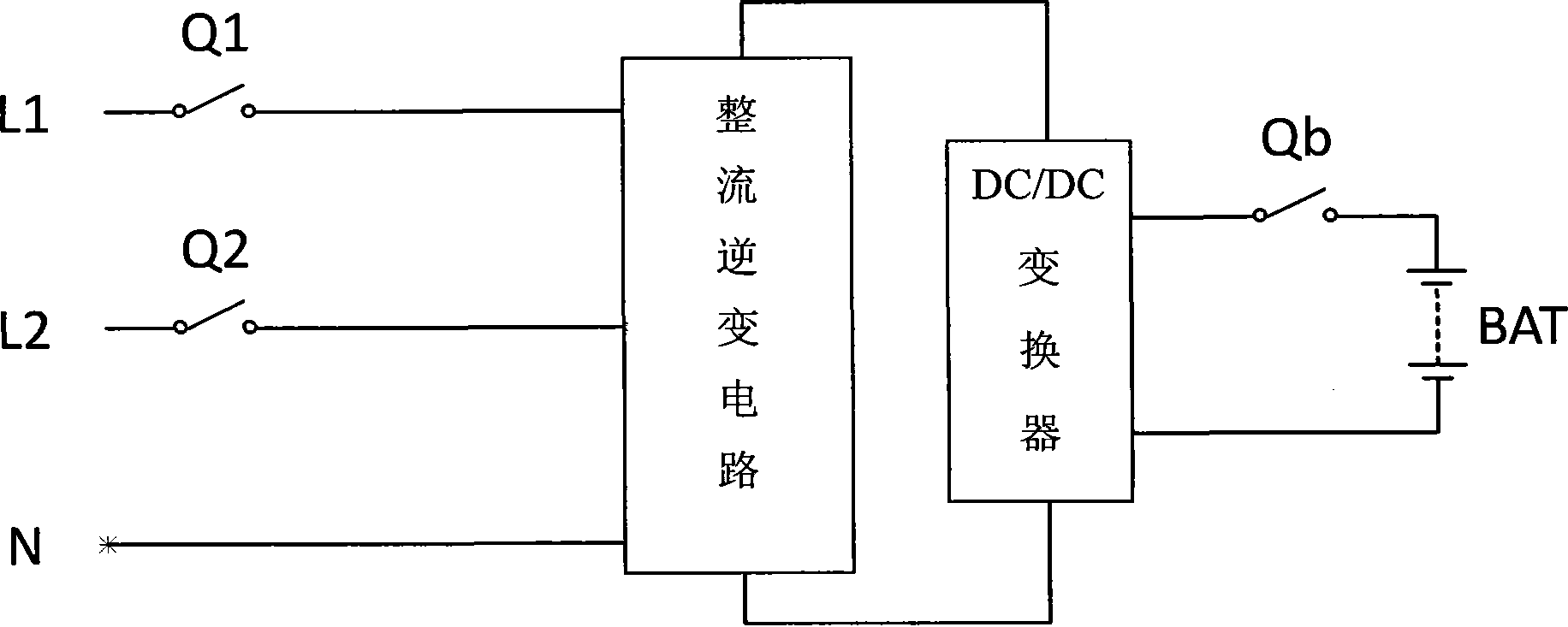
technical field [0001] The invention relates to UPS power supply technology, more specifically, relates to a UPS battery discharge circuit which improves the connection mode of the UPS battery. Background technique [0002] With the increasing demand for data protection, UPS systems have been used more and more widely. In the UPS system, one of the important parts is the discharge circuit of the battery. The battery discharge circuit, especially the topology selection of the battery discharge circuit of UPS in the small and medium power range (about 10KVA), has an important impact on the cost of the whole machine. [0003] At present, for the topological schemes of small and medium power UPS battery discharge circuits, according to the different battery voltages, there are mainly several schemes such as isolated boost, shared PFC and independent BOOST boost. figure 1 and figure 2 Shown are two commonly used battery connection methods for sharing the PFC UPS battery disch...

Claims


Application Information

Patent Timeline
IPC IPC(8): H02J7/02
Inventor 豆飞进
Owner EMERSON NETWORK POWER CO LTD
Learn More