Secondary series type permanent-magnet speed governor

A permanent magnet speed governor, series-type technology, applied in the direction of asynchronous induction clutch/brake, etc., can solve the problems of inconvenient adjustment, large space occupation, and long adjustment distance of the regulator, so as to reduce the occupied space and shorten the adjustment distance , the effect of convenient adjustment

Inactive Publication Date: 2010-09-15
南京艾凌节能技术有限公司
View PDF4 Cites 21 Cited by
  • Summary
  • Abstract
  • Description
  • Claims
  • Application Information

AI Technical Summary

Problems solved by technology

[0004] When designing a high-power permanent magnet governor, in order to increase the effective area, the conductor must be widened, resulting in: the adjustment distance of the regulator is too long, it takes up a lot of space, and the adjustment is inconvenient

Method used


Image

  • Secondary series type permanent-magnet speed governor
  • Secondary series type permanent-magnet speed governor
  • Secondary series type permanent-magnet speed governor

Examples


Embodiment Construction

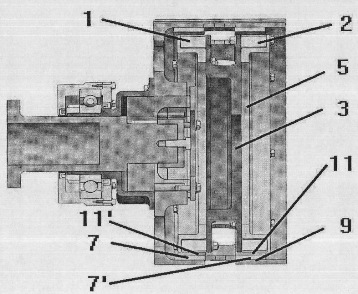
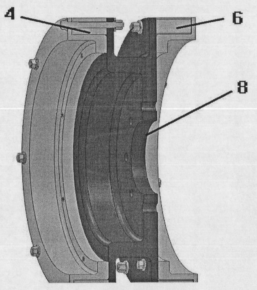
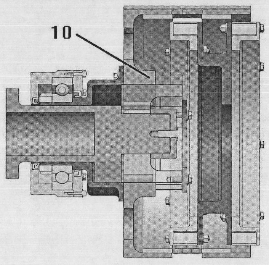
[0016] Reference attached Figure 1~4 :

[0017] The permanent magnet rotor 8 is designed as a two-stage series type, and its structure includes a left magnet rotor 1, a right magnet rotor 2 and a magnet support frame 3. The left magnetic rotor 1 and the right magnetic rotor 2 are respectively mounted on both sides of the magnet support frame 3, and both are composed of a magnetic base 4 with a magnet 6 installed and a stepped baffle 5. The magnetic base 4 has a ring shape, and a magnet 6 is mounted on the outer ring. One end of the stepped baffle 5 is connected with the outer surface of the magnetic base 4 and the other end is connected with the magnet support frame 3. The magnet support frame 3 is a fork-shaped structural component whose outer walls on both sides are respectively connected with the left and right magnetic rotors 1, 2, the middle part is cylindrical, and the bottom of the cylinder is connected with the load shaft.

[0018] The conductor 77' of the cylindrical c...


PUM


Abstract

The invention relates to a secondary series type permanent-magnet speed governor comprising a cylindrical conductor rotor body, a permanent-magnet rotor and a regulator, wherein the permanent-magnet rotor and the cylindrical conductor rotor body are in secondary series types, and the conductor rotor can regulate an active area into 0 or 100 percent by only moving the width of a conductor in order to greatly shorten a regulation distance.

Description

Technical field [0001] The invention relates to a permanent magnet speed regulating device. Specifically, it is a two-stage series permanent magnet governor. Background technique [0002] The applicant previously applied for a patent number of 01000678.7, which published a permanent magnet speed regulator. It includes: a cylindrical conductor rotor, a cylindrical permanent magnet rotor and a regulator. The cylindrical conductor rotor is installed on the motor shaft and rotates synchronously with the motor, and the conductor is installed on it; the cylindrical permanent magnet rotor is installed on the square circular shaft and rotates synchronously with the load shaft, with permanent magnets installed on it; both sides of the square circular shaft There are counterbores to accommodate the motor shaft and the load shaft; the regulator is connected to the permanent magnet rotor and is responsible for adjusting the effective area between the cylindrical conductor rotor and the cyl...

Claims


Application Information

Patent Timeline
Patent Type & Authority Applications(China)
IPC IPC(8): H02K49/04
Inventor 不公告发明人
Owner 南京艾凌节能技术有限公司
Why Eureka
Try Eureka