Visibility-adjustable adaptive optical fundus camera

A technology of adaptive optics and dioptric adjustment, which is applied in the fields of ophthalmoscope, application, medical science, etc., can solve the problems of difficult operation and large adjustment range of the objective lens, so as to improve the imaging quality, facilitate the actual operation, and reduce the adjustment. effect of distance

Inactive Publication Date: 2014-12-24
CHANGCHUN INST OF OPTICS FINE MECHANICS & PHYSICS CHINESE ACAD OF SCI
View PDF8 Cites 0 Cited by
  • Summary
  • Abstract
  • Description
  • Claims
  • Application Information

AI Technical Summary

Problems solved by technology

[0004] In order to solve the problem that the existing imaging system has a large adjustment range of the eyepiece objective lens, resulting in difficult practical operation, the present invention provides an adaptive optics fundus camera with visibility adjustment

Method used


Image

  • Visibility-adjustable adaptive optical fundus camera
  • Visibility-adjustable adaptive optical fundus camera
  • Visibility-adjustable adaptive optical fundus camera

Examples


specific Embodiment approach 1

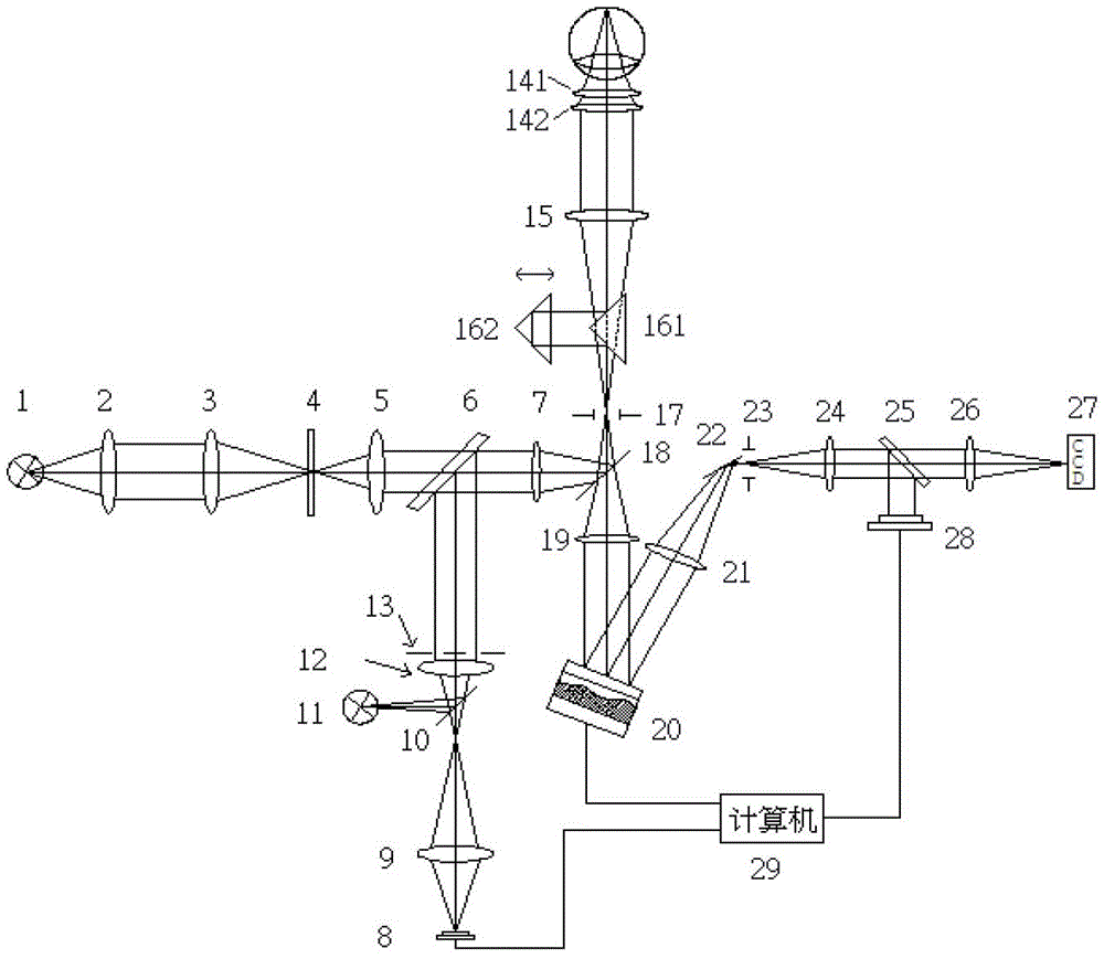
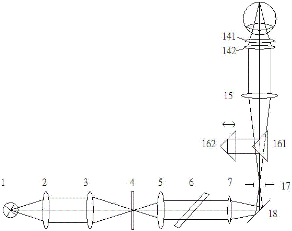
[0012] Specific implementation mode 1. Combination Figure 1 to Figure 3 Describe this embodiment, an adaptive optics fundus camera with visibility adjustment, including an illumination optical system, a diopter adjustment optical system, and an adaptive optics imaging system, respectively adopting the illumination optical system, diopter adjustment optical system, and adaptive optics The imaging system performs triple aberration correction on the human eye;

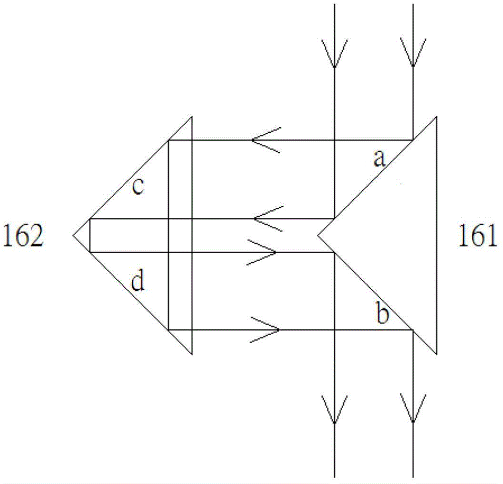
[0013] The diopter adjustment optical system includes a laser light source 1, a first lens 2, a second lens 3, a reticle 4, a third lens 5, a first dichroic coupler 6, a relay mirror 7, and a hollow mirror 18 , the first filter pinhole 17, the inner focusing rectangular prism group 16, the eyepiece objective lens 15 and the pre-correction lens group 14; the visible light emitted by the laser light source 1 is expanded by the first lens 2 and converged by the second lens 3 to illuminate the branch Reticle 4; Reticle 4 is...

specific Embodiment approach 2

[0020] Specific embodiment two, combine Figure 1 to Figure 3 Describe this embodiment, this embodiment is the working process of an adaptive optics fundus camera with visibility adjustment described in the first embodiment:

[0021]First, adjust the diopter of the human eye; equip corresponding spherical mirror 141 and cylindrical mirror 142 according to the degree of visual acuity of the inspected human eye, and rotate the cylindrical mirror 142 so that the human eye can easily see distant objects clearly. Then the equipped spherical mirror 141 and cylindrical mirror 142 are fixed in front of people's eyes. At this time, the He-Ne laser as the light source 1 of the visual mark emits beacon light, which is collimated and enlarged by the first lens 2 and the second lens 3 to illuminate the reticle 4 . The crosshairs on the reticle 4 are imaged at the first filter aperture 17 through the conjugate lens group (the third lens 5 and the relay mirror 7 ). The human eye equipped w...


PUM


Abstract

A visibility-adjustable adaptive optical fundus camera relates to the field of fundus microimaging and solves the problem that an existing imaging system is large in adjusting range of an objective lens to enable actual operation to be difficult. The visibility-adjustable adaptive optical fundus camera comprises a lighting optical system, a diopter regulating optical system and an adaptive optical imaging system. Firstly, primary abebrration of the human eye can be corrected by a pre-correcting lens assembly arranged in front of the human eye, then the tested human eye stares at a sighting mark in the diopter regulating optical system, the human eye can clearly see the sighting mark through automatic focusing of the human eye and regulation of a focus rectangular prism to correct residual primary abebrration of the human eye, finally a Hartmann sensor in the imaging optical system is utilized to detect the wave abebrration of the human eye, and a multi-drive unit deformation lens is utilized to correct high order abebrration of the human eye. The primary abebrration of the human eye can be greatly reduced by the former two diopter regulation steps to enable the residual abebrration to be in an adaptive optical correcting range in the third step, and accordingly a correcting range of the fundus camera is widened.

Description

technical field [0001] The invention relates to the field of fundus microscopic imaging, in particular to an optical fundus camera based on an adaptive optics system and equipped with a vision correction system. Background technique [0002] By observing the retinal capillaries of the human eye, the patient's retinopathy and changes in the systemic microcirculation system can be correctly diagnosed. However, the human eye is a complex optical system, and even normal human eyes inevitably have certain aberrations. The main sources of human eye aberration are as follows: 1. The refractive index of each refractive medium inside the human eye is uneven; 2. The thickness of each refractive medium inside the human eye is uneven, and the surface curvature deviation of different human eyes is serious; 3. The refractive media of the eyes are not on the same axis; 4. The dispersion of the human eye is serious, and the refractive index deviation of the refractive media for each color ...

Claims


Application Information

Patent Timeline
Patent Type & Authority Patents(China)
IPC IPC(8): A61B3/15A61B3/12
Inventor 巩岩李春才
Owner CHANGCHUN INST OF OPTICS FINE MECHANICS & PHYSICS CHINESE ACAD OF SCI
Why Eureka
Try Eureka