
A linear path guidance method for a single steering wheel rear drive mobile platform

A straight-line path, mobile platform technology, applied in vehicle position/route/height control, motor vehicle, non-electric variable control, etc. The effect of guiding accuracy, shortening adjustment distance, and reducing overshoot

Active Publication Date: 2021-07-09
WUHU HIT ROBOT TECH RES INST
View PDF11 Cites 0 Cited by
  • Summary
  • Abstract
  • Description
  • Claims
  • Application Information

AI Technical Summary

Problems solved by technology

[0003] When the main steering wheel is driven in the front (that is, pulling the car body to walk), its motion control is relatively simple, and the correction of the pose is relatively rapid; but when the main steering wheel is driven in the rear (that is, pushing the car body to walk), its motion control is relatively simple. Complicated, when the pose deviates, the correction response speed is slow and prone to overshoot and oscillation
In some cases (such as when the forklift is forklifting, the gear must be in the front), the car body can only be driven by the rear of the main steering wheel, so the pose deviation correction model of the single steering wheel rear-drive forklift is studied. Most of them integrate the PID idea into the conventional fuzzy control. Although it can improve the walking accuracy and stability of the mobile platform, the control effect depends largely on the formulation of fuzzy control rules and membership functions. It largely depends on experience, it is troublesome to determine the relevant parameter values, and there is a lack of corresponding theoretical basis

Method used


Image

  • A linear path guidance method for a single steering wheel rear drive mobile platform
  • A linear path guidance method for a single steering wheel rear drive mobile platform
  • A linear path guidance method for a single steering wheel rear drive mobile platform

Examples


Embodiment Construction

[0029] In order to make the object, technical solution and advantages of the present invention clearer, the present invention will be further described in detail below in conjunction with the accompanying drawings and embodiments. It should be understood that the specific embodiments described here are only used to explain the present invention, not to limit the present invention.

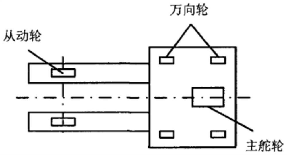
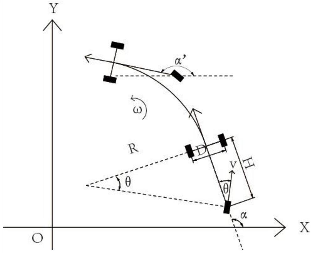
[0030] In the embodiment of the present invention, the single steering wheel drives the forklift model such as figure 1 As shown, the simplified motion model is as follows figure 2 as shown, figure 2 D is the distance between the two driven wheels of the forklift, H is the distance from the active steering wheel to the center of the driven wheel, α is the angle between the vehicle body and the positive direction of the X-axis, θ is the angle between the steering wheel and the vehicle body (right deviation is positive), v is the linear velocity of the active steering wheel, R is the instantaneou...


PUM


Abstract

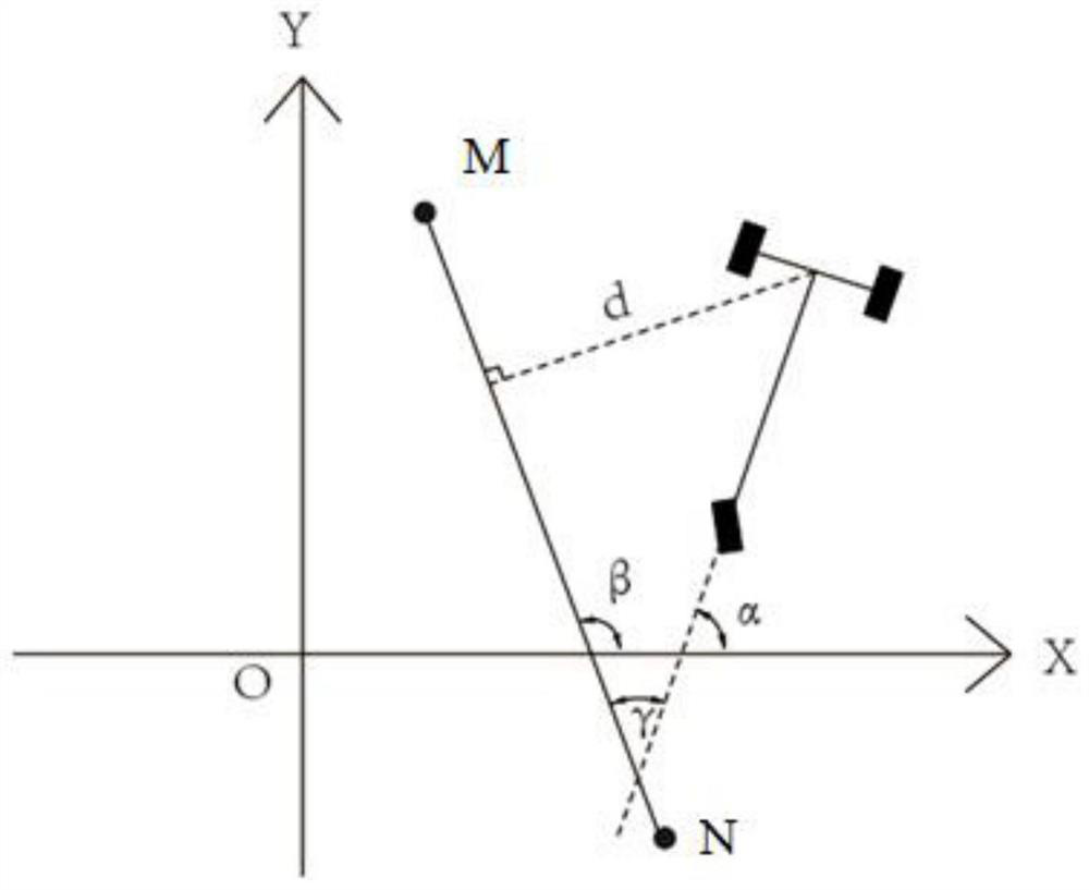
The present invention is applicable to the technical field of automatic control, and provides a linear path guiding method for a single steering wheel rear-drive mobile platform. The method includes the following steps: S1. Real-time detection of the current pose deviation of the forklift, and the pose deviation includes: The lateral distance d that deviates from the expected trajectory, the angle γ that the forklift body currently deviates from the expected trajectory; S2. Keep the linear velocity of the steering wheel unchanged, input the current pose deviation into the calculation model of the steering wheel deflection angle, and output the steering wheel at the next moment declination. The calculation model of the steering wheel deflection angle is constructed through the relevant parameters of the forklift, and the steering wheel deflection angle is adjusted to drive in the direction of the desired track through the calculation model of the steering wheel deflection angle, which reduces the dependence on empirical parameters and improves the guidance accuracy of the mobile platform. The adjustment distance is shortened, the overshoot is reduced, and the calculation model based on the determined steering wheel deflection angle facilitates the debugging of the empirical parameter h.

Description

technical field [0001] The invention belongs to the technical field of automatic control and provides a linear path guiding method for a single steering wheel rear-drive mobile platform. Background technique [0002] Smart forklifts and AGV (Automated Guided Vehicle) are important transportation tools for industrial 4.0 smart factories. They are mainly used to realize the storage and transfer of raw materials, semi-finished products and finished parts, and provide an important guarantee for the flexibility and intelligence of the production system. It also provides technical support for the system to maintain efficient and stable operation. In recent years, trackless navigation is gradually replacing traditional tracked navigation (such as magnetic guide rail) with its advantages of high path flexibility, good controllability, and simple site layout. Its implementation methods include laser radar navigation, infrared top mark sensor navigation Wait. [0003] When the main ...

Claims


Application Information

Patent Timeline
Patent Type & Authority Patents(China)
IPC IPC(8): G05D1/02
CPCG05D1/0223
Inventor 张松涛李超曹雏清高云峰
Owner WUHU HIT ROBOT TECH RES INST
Learn More