
Dead zone compensating method under low frequency based on high voltage large power frequency converter

A dead-time compensation and frequency converter technology, applied in the field of compensation, can solve problems such as system voltage waveform distortion, and achieve the effect of eliminating high-order harmonic content and preventing system oscillation

Inactive Publication Date: 2010-09-15
DONGFANG HITACHI CHENGDU ELECTRICAL CONTROL EQUIP CO LTD
View PDF4 Cites 13 Cited by
  • Summary
  • Abstract
  • Description
  • Claims
  • Application Information

AI Technical Summary

Problems solved by technology

[0004] The purpose of the present invention is to overcome the defect that the system voltage waveform is distorted due to the influence of the dead zone of the current high-voltage and high-power inverter at low frequencies, and to provide a low-frequency dead-zone compensation method based on the high-voltage and high-power inverter

Method used


Image

  • Dead zone compensating method under low frequency based on high voltage large power frequency converter
  • Dead zone compensating method under low frequency based on high voltage large power frequency converter
  • Dead zone compensating method under low frequency based on high voltage large power frequency converter

Examples


Embodiment

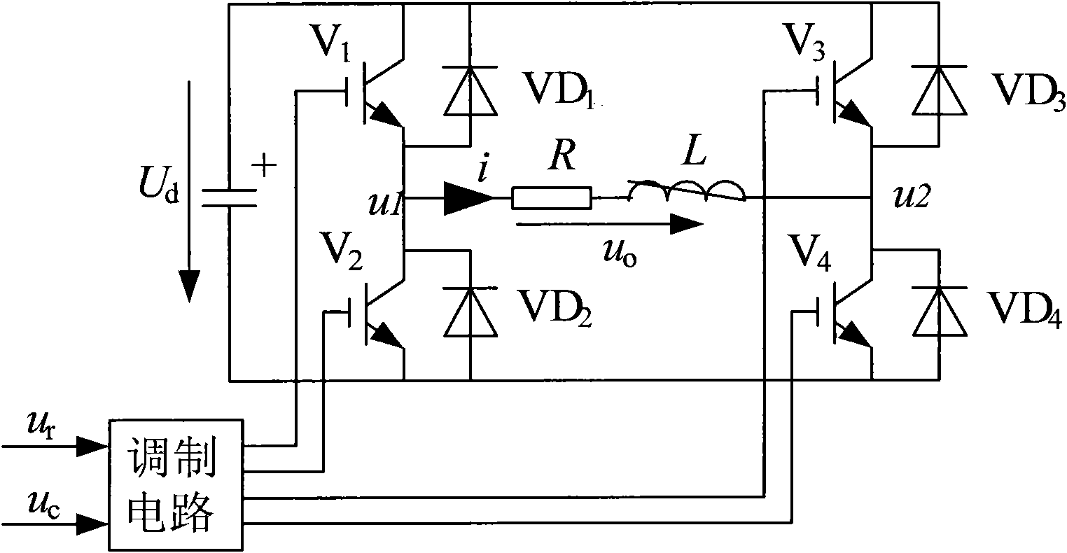
[0027] figure 1 is the topological structure inside a single unit of the present invention, wherein, the signal wave u r and carrier u c Together, they are respectively input to the bases of the power switching device V1, the power switching device V2, the power switching device V3 and the power switching device V4 after being passed through the modulation circuit. At the same time, between the collector and the emitter of the power switching device V1, between the collector and the emitter of the power switching device V2, between the collector and the emitter of the power switching device V3, and between the collector and the emitter of the power switching device V4 A freewheeling diode VD1 , diode VD2 , diode VD3 and diode VD4 are respectively connected in parallel between the emitters.

[0028] The connection point between the emitter of the power switching device V1 and the collector of the power switching device V2 is also connected to the connection point between the ...


PUM


Abstract

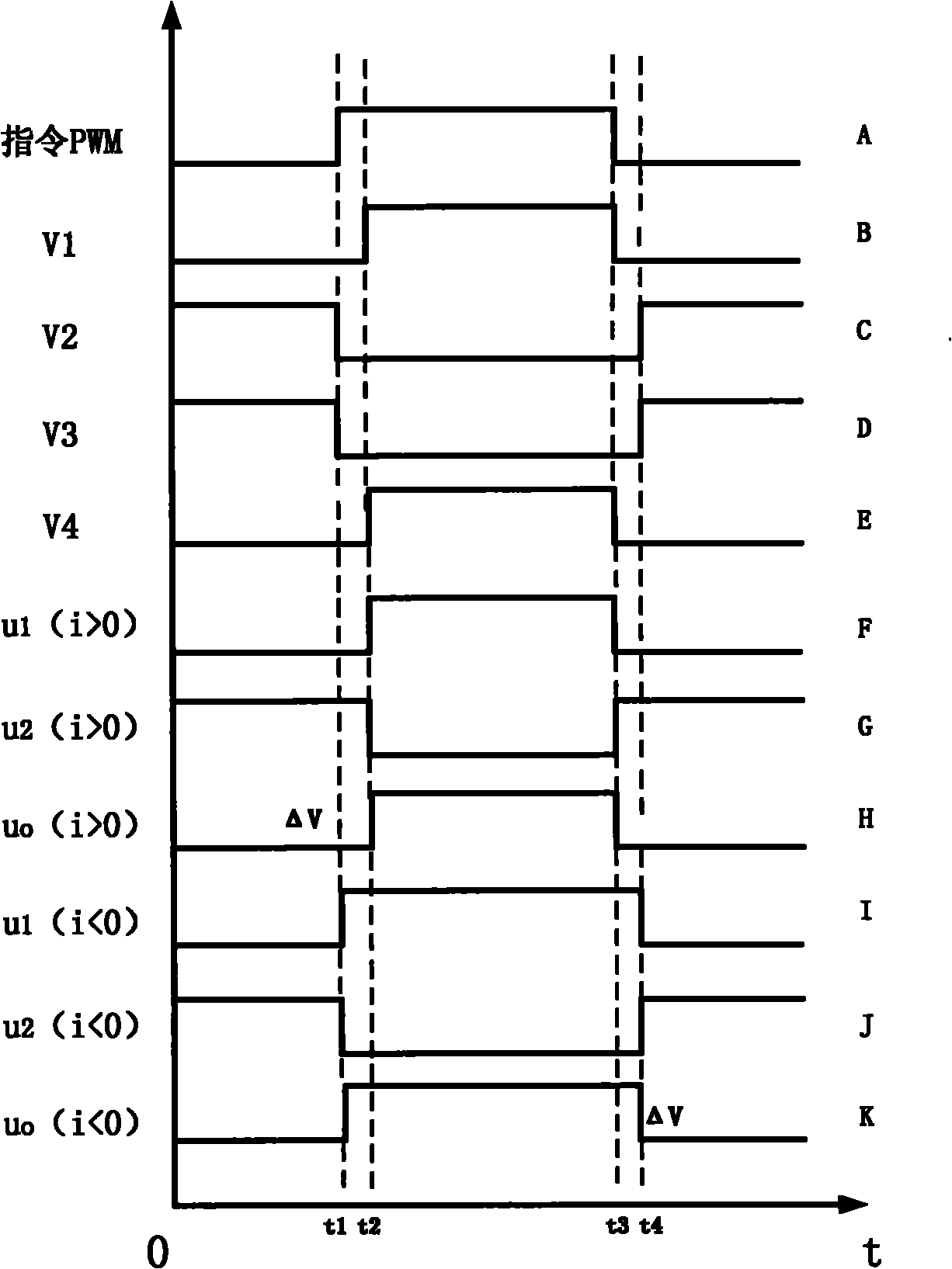
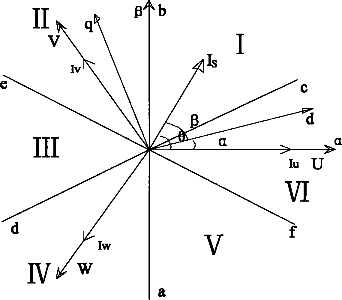
The invention discloses a dead zone compensating method under a low frequency based on a high voltage large power frequency converter, which is characterized by mainly comprising the following steps: (a) starting the frequency converter, and collecting U and V two-phase current values iu and iv from stator current when the revolving speed of the frequency converter reaches a given frequency ranging from 1Hz to 60 Hz; (b) calculating the values of current components id and iq and an angle beta according to a 3S / 2R conversion formula; (c) calculating the value of a current vector angle theta according to the values of the current components id and iq, and judging the section in which current vector is located in a circle according to the vector angle theta; (d) judging positive and negative directions of each phase current by a CPU according to the section in which the stator current vector is is located; and (e) sending a compensated instruction waveform to each processing unit of the frequency converter by the CPU according to the positive and negative directions of each phase current obtained in step (d), and returning to step (a). The dead zone compensating method can reduce or eliminate higher harmonic content of the uncompensated output voltage, and effectively prevent a motor from generating impulse torque or severe system oscillation under some special frequency.

Description

technical field [0001] The invention relates to a compensation method, in particular to a low-frequency dead zone compensation method based on a high-voltage and high-power frequency converter. Background technique [0002] At present, for general-purpose VVVF frequency converters, the control of the motor stator voltage is mostly carried out in an open-loop manner. According to a certain method, the controller outputs the expected value of the stator voltage of the motor, outputs the PWM command after being modulated by the PWM modulation link, and then connects to the control pole of the power switching device of the system inverter unit through the drive circuit to control the output voltage of the inverter unit. If both the PWM modulation link and the inverter unit can work as expected, the open-loop control method of the stator voltage can obtain a relatively ideal control effect. However, due to the inherent switching time of the power device of the inverter unit of t...

Claims


Application Information

Patent Timeline
Patent Type & Authority Applications(China)
IPC IPC(8): H02M1/12H02P27/08
Inventor 赖成毅郑成阳张川唐斌
Owner DONGFANG HITACHI CHENGDU ELECTRICAL CONTROL EQUIP CO LTD
Learn More