
Head-mounted voice transceiver

A transceiver and helmet-type technology, which is applied in the field of helmet-type voice transceivers, can solve the problems of the wearer, such as pain, high airflow friction, and inability to wear for a long time, so as to achieve a comfortable wearing effect

Inactive Publication Date: 2010-09-15
上海登堡信息科技发展有限公司
View PDF3 Cites 8 Cited by
  • Summary
  • Abstract
  • Description
  • Claims
  • Application Information

AI Technical Summary

Problems solved by technology

[0003] One is to install an ordinary microphone in the helmet close to the mouth, and use the ordinary microphone to directly pick up the sound; but because the helmet mask is very close to the mouth, the microphone is sandwiched between the helmet mask and the user's mouth, and when the wearer speaks The airflow sprayed on the microphone will cause a serious popping sound, so it is difficult for the receiver to recognize the voice; and for the helmet with a non-full airtight mask, the airflow at the bottom of the motorcycle will rush into the microphone when the motorcycle is running at high speed, resulting in strong wind noise interference
[0004] The other is to install a contact microphone on the top of the helmet, and use the weight of the helmet to make the contact microphone close to the top of the wearer's head to collect bone conduction voice signals; however, due to the heavy weight of the helmet, the contact microphone will oppress the wearer The top of the head causes pain at the pressure point of the wearer, so it cannot be worn for a long time; and when the motorcycle is running, the airflow friction on the top of the helmet is relatively large, and the foam buffer layer on the top of the helmet can only play a buffering role, and cannot isolate friction and vibration Therefore, it will cause strong wind noise interference and affect the call quality

Method used


Image

  • Head-mounted voice transceiver
  • Head-mounted voice transceiver
  • Head-mounted voice transceiver

Examples


Embodiment Construction

[0025] The embodiments of the present invention will be further described in detail below in conjunction with the accompanying drawings, but the present embodiments are not intended to limit the present invention, and any similar structures and similar changes of the present invention should be included in the protection scope of the present invention.

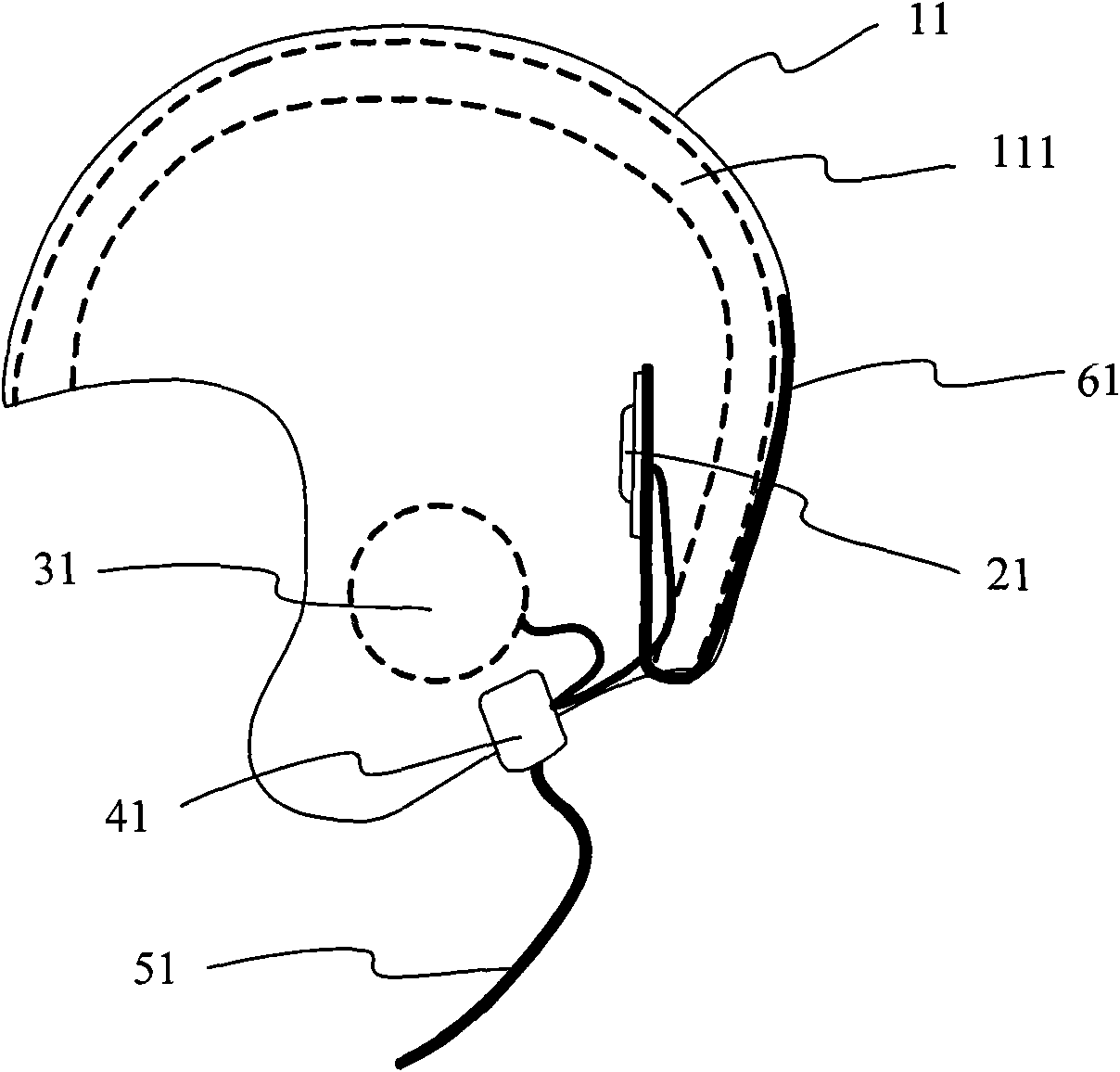
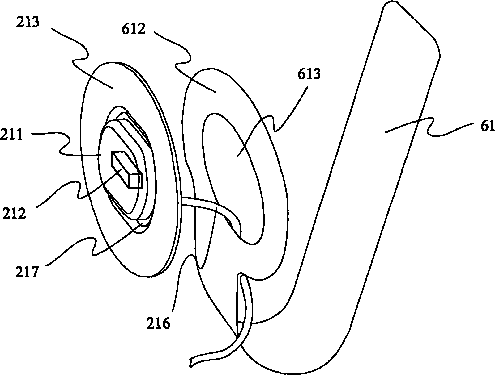
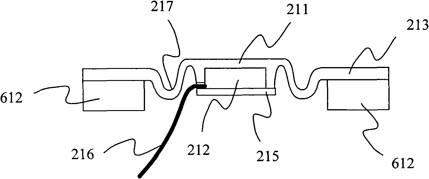
[0026] Such as figure 1 As shown, a helmet type voice transceiver provided by the first embodiment of the present invention is characterized in that it includes a helmet 11, a contact microphone assembly 21, a connecting part, a loudspeaker 31 and a splitter 41; the contact microphone The component 21 is installed on the back of the head inside the helmet 11 through the connecting parts, and its contact surface faces the inner cavity of the helmet 11. The speaker 31 is installed on the ear part inside the helmet 11, and the splitter 41 is installed on the helmet. 11, and connect the contact microphone assembly 21 and the louds...


PUM


Abstract

The invention relates to a head-mounted voice transceiver, and relates to the technical field of voice transceivers, which solves the technical problems of poor call quality and uncomfortable wearing during the driving of motorcycles in the prior art. The voice transceiver is characterized by comprising a helmet, a contact microphone component, an interconnecting piece, a speaker and a deconcentrator, wherein the contact microphone component is arranged at an afterbrain position or a cheekbone position on the inner side of the helmet through the interconnecting piece, a contact surface of the contact microphone component faces an inner cavity of the helmet and can move elastically relative to the inner wall of the helmet; the speaker is arranged at an ear position of the inner side of the helmet; the deconcentrator is arranged on the helmet, and is connected with the contact microphone component and the speaker through a cable; and the deconcentrator is provided with a lead-out cable for connecting communication equipment. When the voice transceiver provided by the invention is utilized, the clear speech communication can be kept during the driving of motorcycles, and the head-mounted voice transceiver wears comfortable.

Description

technical field [0001] The invention relates to the technology of a voice transceiver, in particular to the technology of a helmet-type voice transceiver used for communication while a motorcycle is running. Background technique [0002] Motorcyclists add microphones to their helmets when they need to communicate on the move. There are currently two ways to install a microphone in a motorcycle helmet: [0003] One is to install an ordinary microphone in the helmet close to the mouth, and use the ordinary microphone to directly pick up the sound; but because the helmet mask is very close to the mouth, the microphone is sandwiched between the helmet mask and the user's mouth, and when the wearer speaks The airflow sprayed on the microphone will cause a serious popping sound, so it is difficult for the receiver to recognize the voice; and for the helmet with a non-full airtight mask, the airflow at the bottom of the motorcycle will rush into the microphone when the motorcycle ...

Claims


Application Information

Patent Timeline
IPC IPC(8): H04M1/02H04B1/38H04R1/02H04B1/3822H04B1/3877H04B1/46
Inventor 胡强李晶
Owner 上海登堡信息科技发展有限公司
Learn More