Knee joint prosthesis system and method for implantation

A box and main body technology, applied in the field of knee joint prosthesis, can solve problems such as bone loss

Active Publication Date: 2010-09-15
BIOMET MFG CORP
View PDF9 Cites 43 Cited by
  • Summary
  • Abstract
  • Description
  • Claims
  • Application Information

AI Technical Summary

Problems solved by technology

Also, in some cases, it may be necessary to induce bone loss in the area adjacent to this knee prosthesis

Method used


Image

  • Knee joint prosthesis system and method for implantation
  • Knee joint prosthesis system and method for implantation
  • Knee joint prosthesis system and method for implantation

Examples


Embodiment Construction

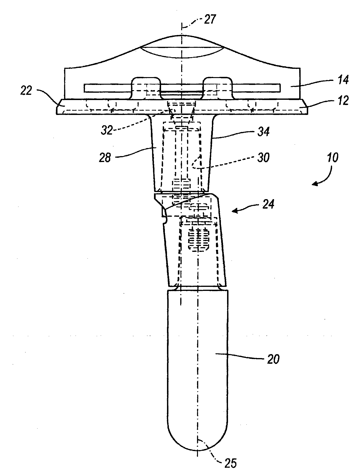
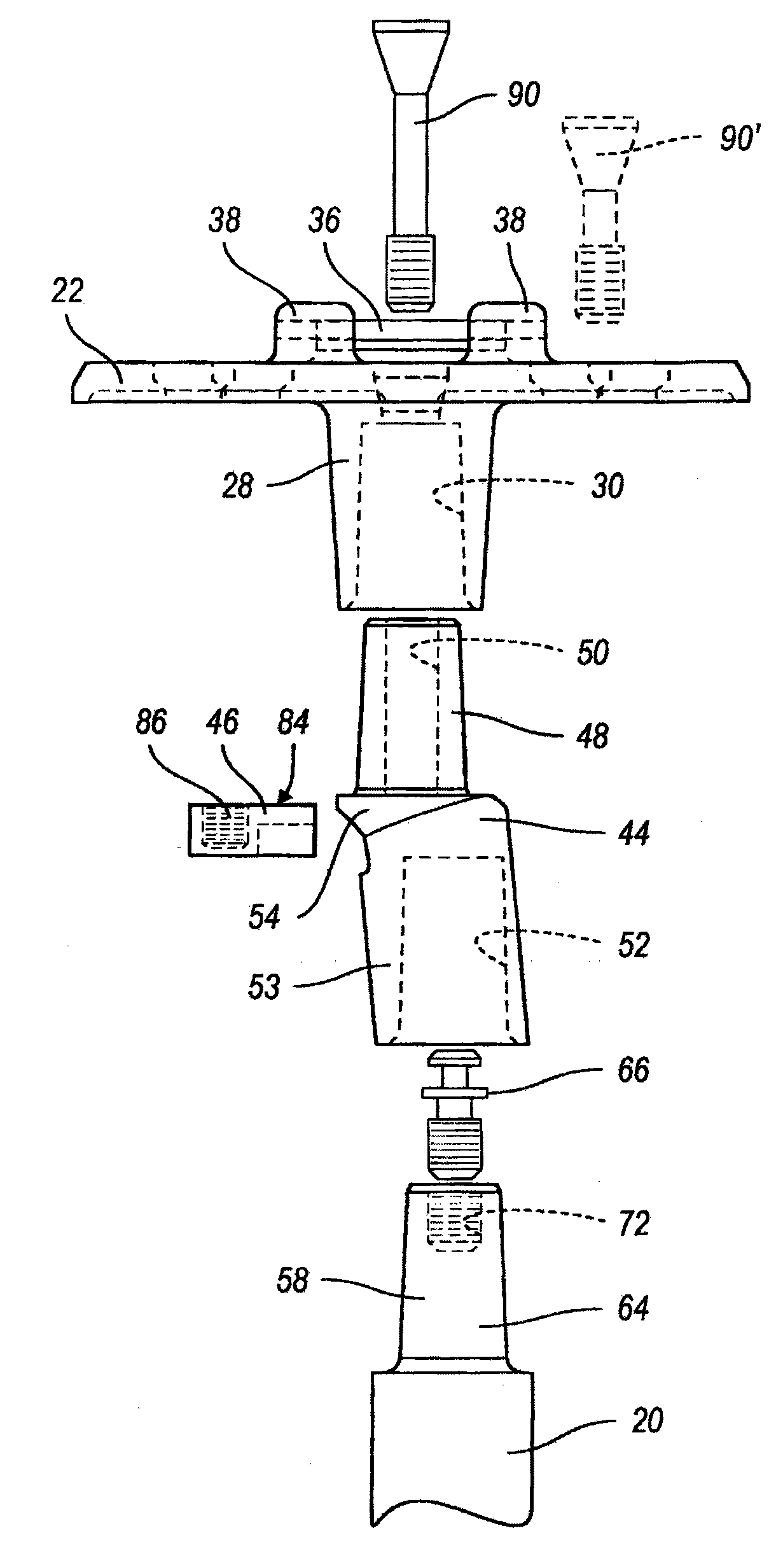
[0076] First, the present disclosure provides a knee prosthesis system having various knee prostheses adaptable for use in knee replacement surgery. Various tibial and femoral components are described for use alone or as part of cruciate fixation (CR) knee replacements, posterior stabilized (PS) knee replacements, fully constrained knee replacements, and hinged knee replacements. As described below, the present disclosure further provides various modular adapters, stems, and augments that can be used in any combination with any of the tibial and femoral components disclosed herein. In other words, all components disclosed above and below the joint line (eg, stems, adapters, augments, etc.) can be used interchangeably with any knee prosthesis disclosed herein and on the tibial or femoral side. Also, selection of any knee prosthesis and associated components from the knee prosthesis system may be selected by the performing surgeon at the time of the procedure.

[0077] see firs...


PUM


Abstract

A system for cooperating with an elongated IM member during preparation of a bone for receiving a prosthesis can include a scaffold, skeleton or frame (1362). An alignment assembly (1364) can be selectively coupled to the frame. The alignment assembly can cooperate with the IM member to position the frame relative to the bone. A cutting block (1366) can be selectively coupled to the frame. According to other features, a posterior stabilized (PS) box guide assembly (1470) can have a PS box guide attachment portion that selectively couples with the first attachment portion of the frame. A posterior foot (1470) can selectively couple with a second attachment portion on the frame. The posterior foot can be positioned to occupy space of a joint line in an installed position.

Description

[0001] Cross References to Related Applications [0002] This application claims priority to U.S. Application 12 / 248,509, filed October 9, 2008, U.S. Application 12 / 248,517, filed October 9, 2008, and to U.S. Serial 11, filed January 10, 2008 Continuing in part of / 972,359 and claiming the benefit of U.S. Provisional Application 60 / 978,949, filed October 10, 2007. The disclosure of the above application is hereby incorporated by reference. technical field [0003] The present disclosure relates generally to knee prostheses, and more particularly to various tibial and femoral components and modular augmentations for cooperation with such tibial and femoral components. Background technique [0004] A knee prosthesis typically includes a femoral component and a tibial component. The femoral and tibial components are designed to be surgically attached to the distal end of the femur and the proximal end of the tibia, respectively. The femoral component is further designed to c...

Claims


Application Information

Patent Timeline
Patent Type & Authority Applications(China)
IPC IPC(8): A61F2/38A61B17/15A61F2/30
CPCA61F2002/30878A61F2002/30604A61F2/30721A61F2002/30344A61F2/385A61B17/1764A61F2/3886A61B17/157A61F2002/30332A61F2/3868A61F2220/0033A61B17/155A61F2002/30736A61F2/38A61F2002/30616A61F2002/30339
Inventor 布莱恩·M·梅杜克·A·福克斯
Owner BIOMET MFG CORP
Why Eureka
Try Eureka