Coaxial two-wheeled vehicle
A two-wheeled, coaxial technology, used in two-wheeled bicycles, bicycles, motorcycles, etc., to achieve the effect of high safety and convenient getting on and off
- Summary
- Abstract
- Description
- Claims
- Application Information
AI Technical Summary
Problems solved by technology
Method used
Image

Examples
no. 1 approach
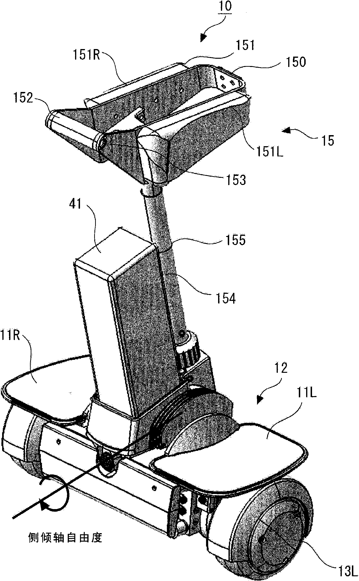
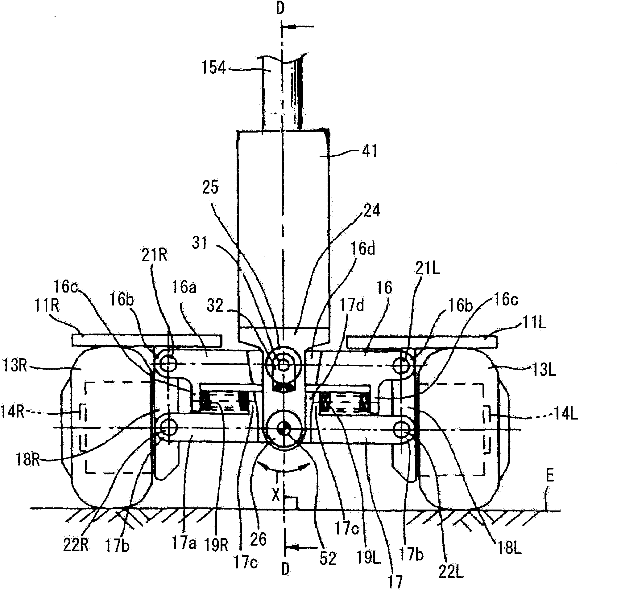
[0060] use figure 1 The perspective view is shown to illustrate the structure of the coaxial two-wheeled vehicle of the first embodiment. In this specification, a pitch axis is an axis corresponding to the axles of the pair of wheels 13L, 13R. The roll axis is an axis passing through the center of the vehicle body 12 and parallel to the traveling direction of the vehicle. A yaw (yaw) axis is an axis passing through the center of the vehicle body 12 and perpendicular to the road surface on which the vehicle is running.
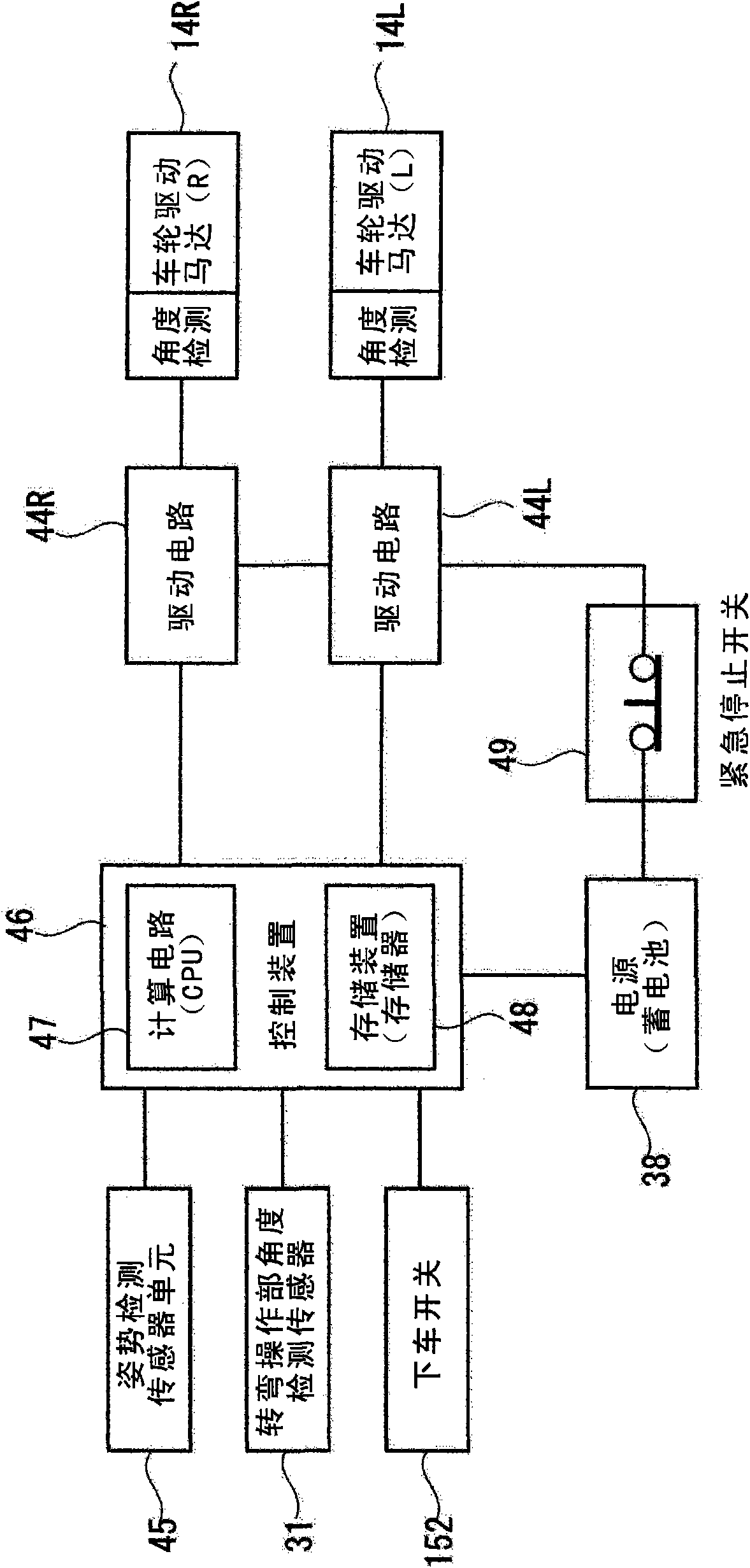
[0061] This coaxial two-wheeled vehicle 10 includes: a vehicle body 12 ; wheels 13L, 13R; wheel drive units 14L, 14R; and a turning operation unit 15 .
[0062] The turning operation unit 15 is an operation means for performing a turning operation by tilting it in a roll direction. The turning operation unit 15 includes: a base member 150 ; knee contact portions 151L, 151R; an operating lever 154 ; and an operating lever height adjusting portion 155 .
[0...
no. 2 approach
[0100] Compared with the first embodiment of the invention, the second embodiment is characterized in that the turning operation part is formed in a novel shape, and an alighting switch is provided near the handle for getting on and off the turning operation part.
[0101] Figure 7 It is an external perspective view of the coaxial two-wheeled vehicle of the second embodiment. The vehicle body 12 of the coaxial two-wheeled vehicle of this second embodiment has the same structure as that of the first embodiment of the invention, and therefore description thereof will be omitted.
[0102]The turning operation portion 45 has a standing portion 451 having a substantially U-shape when viewed from the front. The upper ends of the vertical pieces 451L, 451R of the standing portion 451 are connected by the handle 452 for getting on and off the vehicle. Further, knee abutment portions 453L, 453R respectively extending rearward are formed continuously on the upper ends of the vertical...
no. 3 approach
[0107] This third embodiment is characterized in that the height of the turning operation portion is lower than that of the first embodiment of the invention.
[0108] Figure 9 It is an external perspective view of the coaxial two-wheeled vehicle of the third embodiment. The vehicle body 12 of the coaxial two-wheeled vehicle of the third embodiment has the same structure as that of the first embodiment of the invention, and therefore description thereof will be omitted.
[0109] The turning operation portion 55 has a ring shape, and its lower end portion is supported so as to be rotatable relative to the vehicle body 12 . Specifically, the turning operation part 55 is integrally formed with the calf contact part 551L, the calf contact part 551R, the carrying handle 552, the lower connection part 553, the quick lever 554L, and the quick lever 554R.
[0110] The calf contact portions 551L and 551R are disposed at positions where they come into contact with each calf of the oc...
PUM
 Abstract
Description
Claims
Application Information
 - R&D
- Intellectual Property
- Life Sciences
- Materials
- Tech Scout
- Unparalleled Data Quality
- Higher Quality Content
- 60% Fewer Hallucinations
Browse by: Latest US Patents, China's latest patents, Technical Efficacy Thesaurus, Application Domain, Technology Topic, Popular Technical Reports.
© 2025 PatSnap. All rights reserved.Legal|Privacy policy|Modern Slavery Act Transparency Statement|Sitemap|About US| Contact US: help@patsnap.com