
Valve

A valve and valve disc technology, applied in the application field of the valve, can solve problems such as bearing and seal damage, and achieve the effect of simplifying positioning and minimizing structural space

Inactive Publication Date: 2010-09-15
CONTINENTAL AUTOMOTIVE GMBH
View PDF1 Cites 2 Cited by
  • Summary
  • Abstract
  • Description
  • Claims
  • Application Information

AI Technical Summary

Problems solved by technology

The disadvantage of such a valve is that contamination or condensate droplets in the flow medium can penetrate into the bearings or seals of the drive shaft and damage them in a disadvantageous manner

Method used


Image

  • Valve
  • Valve
  • Valve

Examples


Embodiment Construction

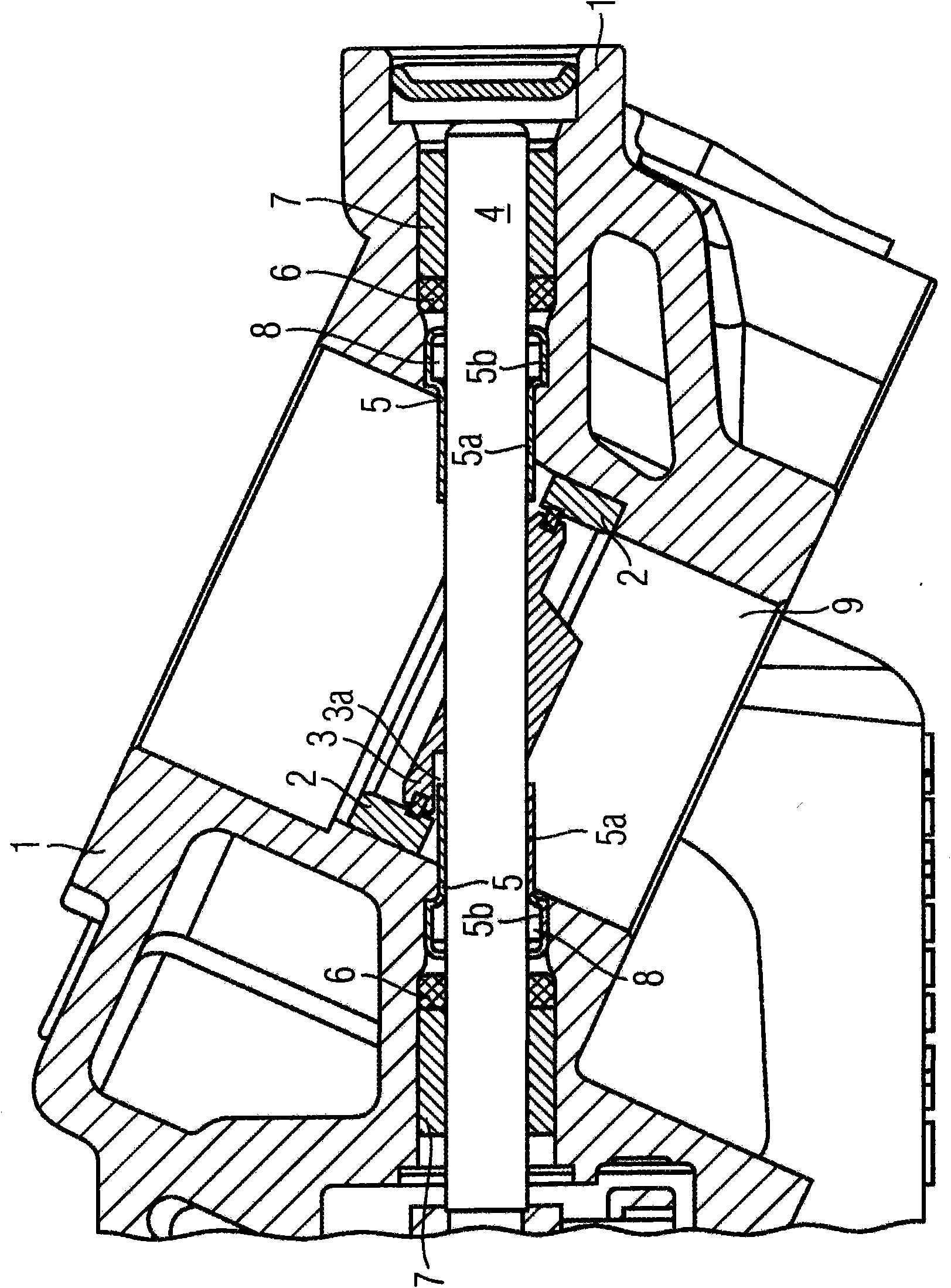
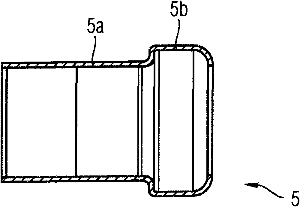
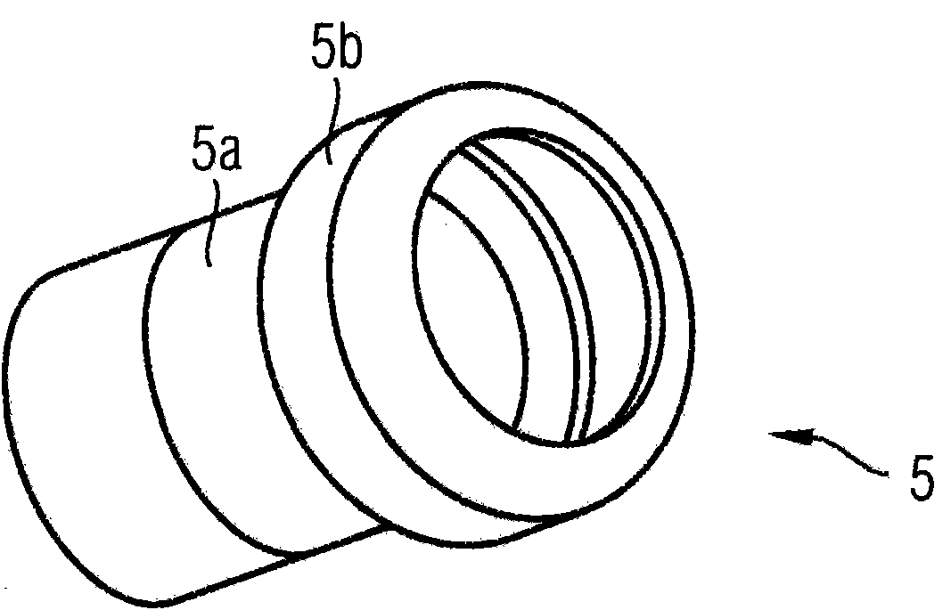
[0016] figure 1 A longitudinal section view of the valve is shown. The valve comprises a housing 1 with a valve seat 2 for a valve flap 3 which is rotatably supported on a drive shaft 4 . The drive shaft 4 is guided through the housing 1 on both sides. In this region, a sleeve 5 is arranged in a stationary manner in the housing 1 , through which sleeve the drive shaft 4 is rotatably guided. The sleeve 5 has a first region 5a which faces the valve flap 3 and surrounds the drive shaft 4 with a first gap. Furthermore, the sleeve 5 has a second region 5 b facing away from the valve flap 3 and having an enlarged diameter compared to the first region 5 a and enclosing the drive shaft 4 with a second gap on its end face facing away from the valve flap 3 . A storage space 8 is formed by the diameter expansion, which is suitable for collecting pollutants or condensed water. An annular seal 6 and a bearing 7 are arranged around the drive shaft 4 in the vicinity of the end face of t...


PUM


Abstract

The valve comprises a housing (1) having at least one valve seat (2) for at least one flap (3), which is supported so it can rotate on a drive shaft (4). The drive shaft (4) is guided on at least one side through the housing (1), a sleeve (5), through which the drive shaft (4) is rotatably guided, being disposed fixed in place on the inside of the housing (1) in this area. The sleeve (5) has a first area (5a), which faces the flap (3) and encloses the drive shaft (4) with a first slight play. Furthermore, the sleeve (5) has a second area (5b), which faces away from said flap (3) and has a diameter expansion in comparison to the first area (5a) and which, on the front side thereof facing away from the flap (3) encloses the drive shaft (4) with a second slight play. Furthermore, the object of the invention is the use of the valve as a gas recirculation valve of a motor vehicle.

Description

technical field [0001] The invention relates to a valve and an application of the valve. Background technique [0002] Valves are known, for example, for gas passages. In DE 10 2005 051 305 A1 a valve is described which comprises a housing with a first valve seat for a first valve flap and a second valve seat for a second valve flap, the valves The petals are rotatably supported on the drive shaft. The drive shaft of the valve is guided through a part of the housing between the first valve flap and the second valve flap. A disadvantage of such valves is that contamination or condensed water droplets in the flow medium can penetrate into the bearings or seals of the drive shaft and damage them in a disadvantageous manner. Contents of the invention [0003] It is therefore the object of the present invention to provide a valve in which the ingress of contaminants or condensation into the bearings and seals of the drive shaft can be avoided as far as possible. The object ...

Claims


Application Information

Patent Timeline
Patent Type & Authority Applications(China)
IPC IPC(8): F16K1/226
CPCF16K1/2268F16K1/22
Inventor 格尔德·博恩曼乌韦·克莱门马库斯·霍伊泽尔
Owner CONTINENTAL AUTOMOTIVE GMBH
Learn More